Assembly to lock a storm curtain adjacent to an opening in a building

a technology for storm curtains and openings, applied in the direction of curtain suspension devices, door/window protective devices, wing accessories, etc., can solve the problems of disfiguring the exterior of the structure, and affecting the safety of passengers

Inactive Publication Date: 2007-12-13
WAYNE DALTON CORP
View PDF28 Cites 56 Cited by
  • Summary
  • Abstract
  • Description
  • Claims
  • Application Information

AI Technical Summary

Benefits of technology

[0011]Yet another aspect of the present invention is to provide an assembly for covering a building opening for preventing debris from entering a building interior, the assembly comprising a header positioned at one end of the building opening, the header having an outer chamber and an inner chamber separated by a sealing wall, and the input being positioned at least partially in the inner chamber, a shaft positioned in the outer chamber of the header, a rotational input mechanism positioned in the inner chamber of the header, wherein the sealing wall prevents moisture and debris from entering the building interior through the header.
[0012]Still another aspect of the present invention is an assembly for covering a building opening, the assembly comprising a shaft positioned at one end of the opening, a cover carried by the shaft, a stop positioned proximate to the shaft, wherein the curtain is coupled to the shaft such that when the curtain is completely unrolled, the stop is adapted to engage the curtain and the shaft and prevent the curtain from counter-winding on the shaft.
[0013]Yet another aspect of the present invention is an assembly for covering a building opening for preventing debris from entering a building interior, the assembly comprising a header positioned at one end of the building opening, the header having an outer chamber and an inner chamber separated by a sealing wall, a shaft positioned in the outer chamber of the header, a curtain carried by the shaft, a locking mechanism at the opposed end of the building opening from the shaft that selectively holds the curtain in a locked position to cover the building opening, an input mechanism positioned at least partially in the inner chamber of the header for selectively rotating the shaft, and a linking assembly adapted to transfer a rotational input from the input mechanism to the shaft to selectively rotate the shaft, wherein the linking assembly includes a failsafe portion designed to fail upon a predetermined impact on the curtain and the sealing wall prevents moisture and debris contacting the input mechanism.

Problems solved by technology

Otherwise, if the high winds or windborne debris breaches the integrity of the structure by destroying a window or door, severe damage to the structure can be expected.
However, this boarding up procedure is not only time consuming, when time is usually of the essence, but also can disfigure the exterior of the structure upon frequent installation and removal.
In addition, plywood has a limited life, particularly after becoming wet.
Finally, storing and maintaining an inventory of plywood sheets can be problematic.
However, these devices are not only costly, but also they do not provide the necessary wind or water resistant seal, irrespective of whether they are mounted on the windward or leeward side of the building.
Because this chamber is frequently exposed to wind and rain, the electronic and motor components must be individually sealed to prevent damage.
The requirement of this additional sealing adds costs to the protection device.
Further, even with the extra seals, durability and reliability is often times a concern.
Other problems exist with these prior art designs.
At times these devices do not prove strong enough or durable enough to withstand the impact of projectiles which may be carried by the high winds.
Further, such prior art systems oftentimes are not capable of easy maintenance and operation because it is difficult to access various working parts.
Still further, these systems are susceptible to failure if a projectile, carried by the high winds, impacts the fabric causing terminal stresses to internal mechanisms.

Method used


Image

  • Assembly to lock a storm curtain adjacent to an opening in a building
  • Assembly to lock a storm curtain adjacent to an opening in a building
  • Assembly to lock a storm curtain adjacent to an opening in a building

Examples


Embodiment Construction

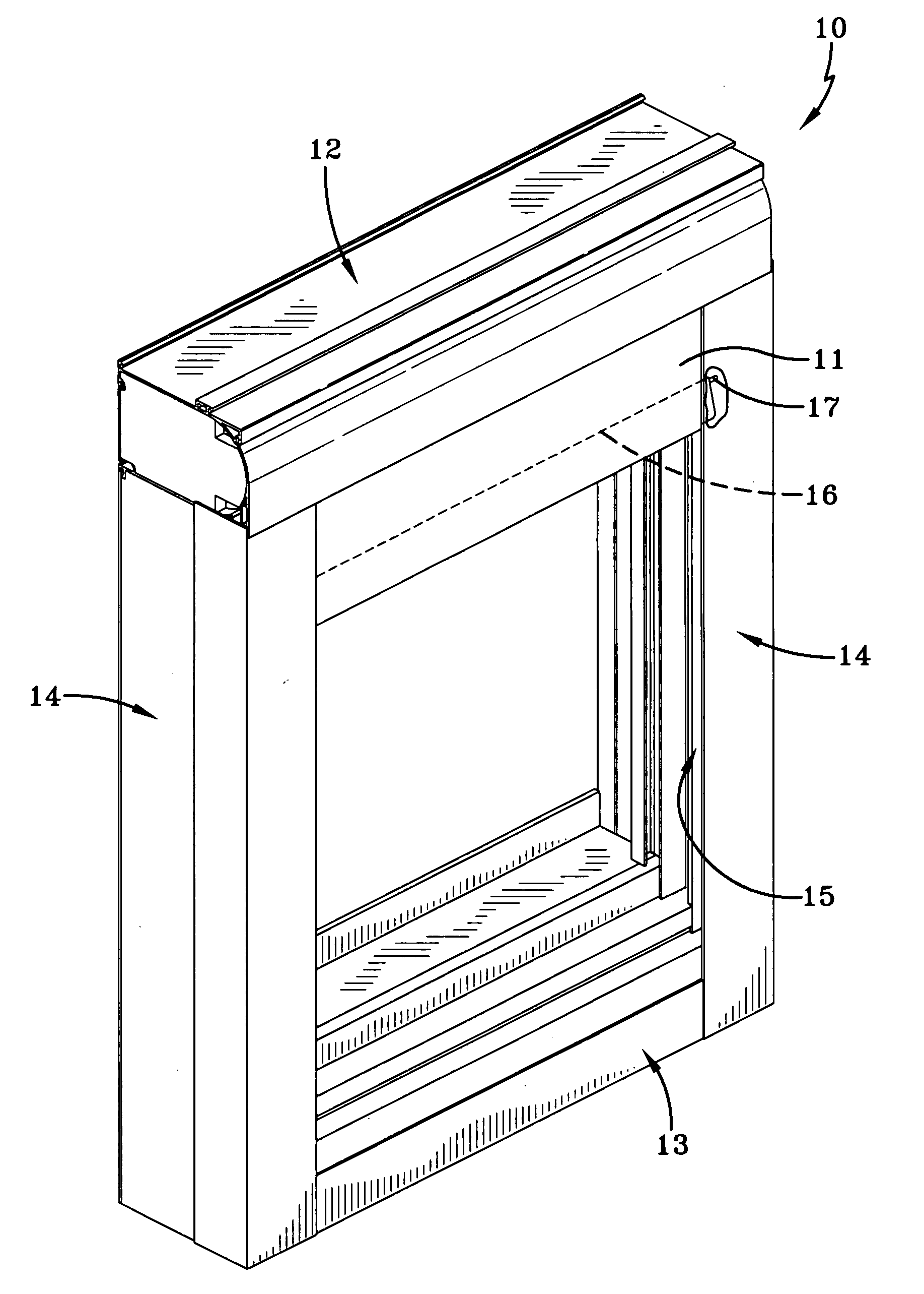
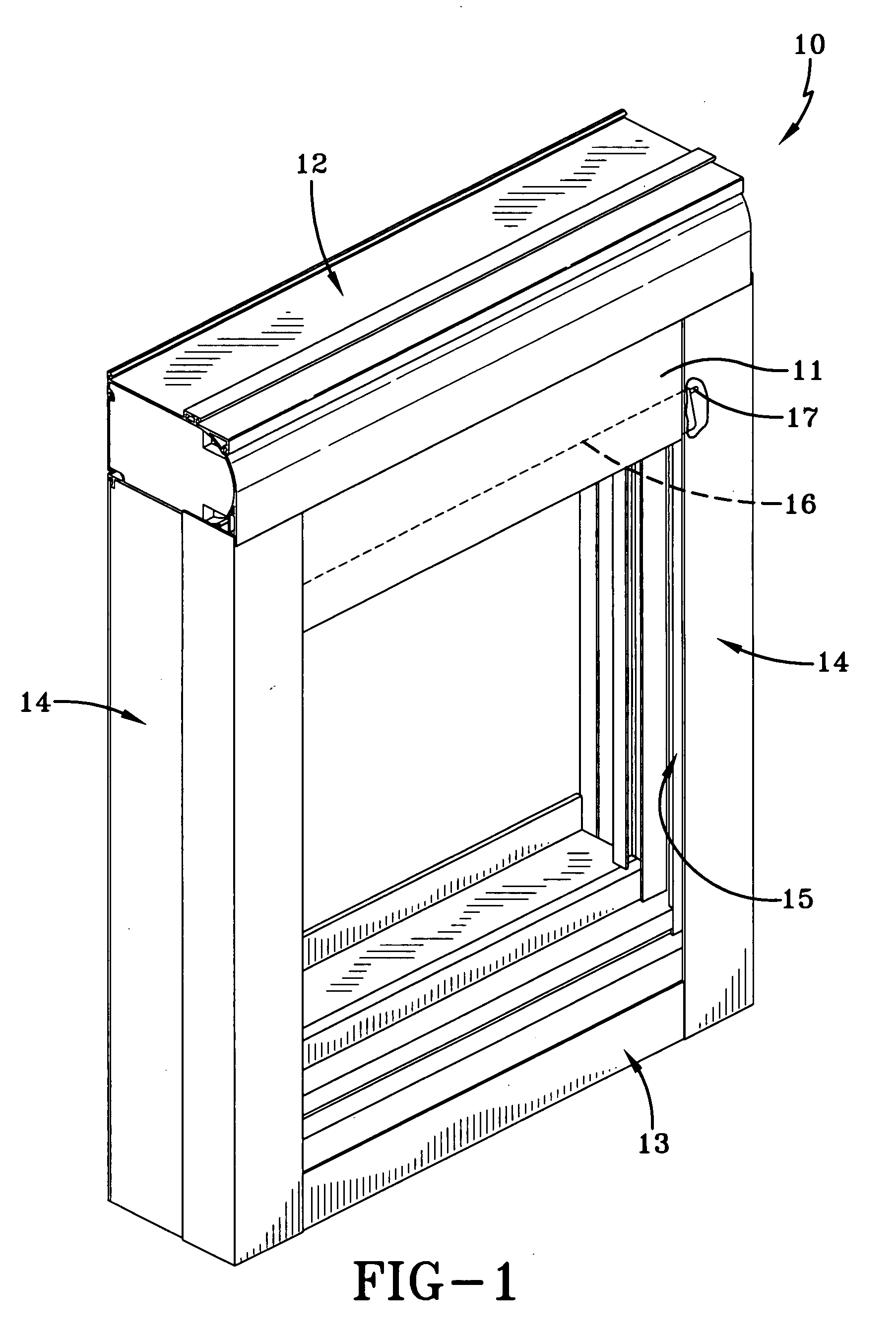
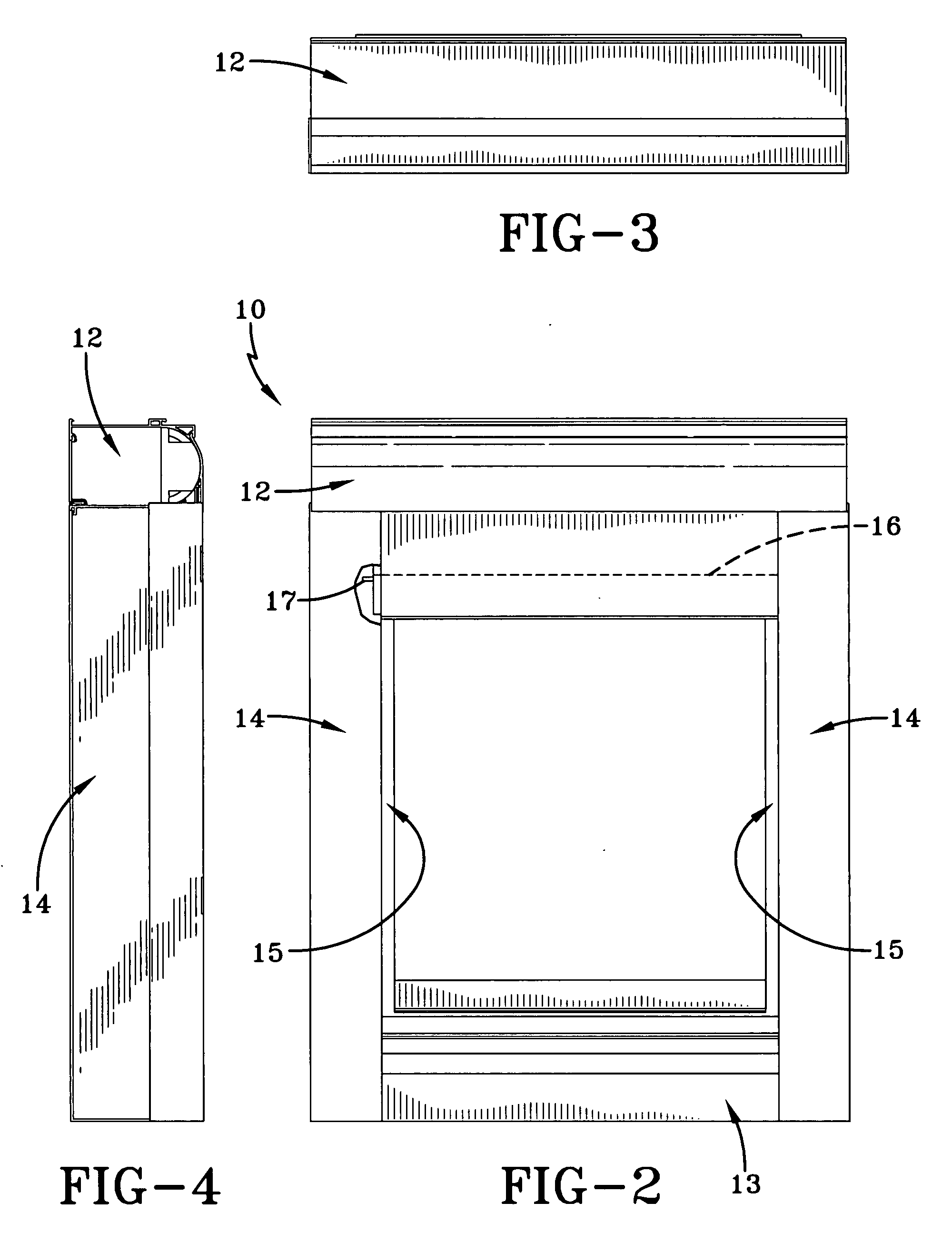
[0081]A storm curtain assembly made in accordance with the present invention is generally indicated by the numeral 10 and includes a fabric curtain 11 which is selectively movable to obstruct a building opening, such as a window, door or the like. Storm curtain assembly 10 selectively prevents solar heat gain and protects the opening from intrusion due to high winds or windborne debris, such as a window. Curtain 11 is made of a material which is water resistant and which can withstand the forces of wind and airborne debris, as are often encountered in a hurricane or the like. Examples of such fabric are disclosed in U.S. patent application Ser. No. 11 / 190,114 filed on Jul. 25, 2005, to which reference is made for whatever details are necessary to understand the present invention. A locking bar 16, which is generally rectangular in the end view, is secured to the bottom end of curtain 11. Bar 16 is rigid and extends across the entire lateral width of curtain 11, providing a sturdy su...


PUM


Abstract

An assembly for covering a building opening that provides a shaft positioned at one end of the building opening, a curtain carried by the shaft, and a locking mechanism at the opposed end of the building opening from the shaft that selectively holds the curtain in a locked position to cover the building opening. The assembly also includes an input for selectively rotating the shaft, and a linking assembly adapted to transfer the input to the shaft to selectively rotate the shaft, wherein the linking assembly includes a failsafe portion designed to fail upon a predetermined impact force on the curtain. An operator is also provided to allow controllable movement of the curtain between the various positions.

Description

CROSS-REFERENCE TO RELATED APPLICATIONS[0001]This application claims the benefit of U.S. Provisional Application No. 60 / 799,902, filed May 12, 2006, and U.S. Provisional Application No. 60 / 816,830, filed Jun. 27, 2006, both of which are incorporated herein by reference.TECHNICAL FIELD[0002]This invention relates to a storm curtain system which selectively obstructs an opening in a structure, such as a window, door or the like. The storm curtain system selectively prevents solar heat gain and protects the opening from intrusion due to high winds or windborne debris.BACKGROUND ART[0003]In geographic areas which are prone to having high wind events, such as hurricanes and the like, the need exists for the protection of openings, such as windows and doors, in buildings. Otherwise, if the high winds or windborne debris breaches the integrity of the structure by destroying a window or door, severe damage to the structure can be expected.[0004]In its most simple form, one type of known pro...

Claims


Application Information

Patent Timeline
Patent Type & Authority Applications(United States)
IPC IPC(8): E05F15/20
CPCE06B9/42E06B2009/005E06B9/86
Inventor MULLET, WILLIS J.HAND, RICHARD S.BRUNK, DARRIN W.PAQUETTE, DEREK S.MAMALOUKAS, JASON L.BARDIN, RICHARD
Owner WAYNE DALTON CORP
Why Eureka
Try Eureka