Composite spars

a technology of composite materials and spars, applied in the field of composite materials, can solve the problems of slow manufacturing process, high cost of cloth/fabric materials, and better performance of composite materials based spars for many applications, and achieve the effect of speeding up production

Active Publication Date: 2011-11-22
GE AVIATION SYST LTD
View PDF20 Cites 44 Cited by
  • Summary
  • Abstract
  • Description
  • Claims
  • Application Information

AI Technical Summary

Benefits of technology

[0015]Various aspects and embodiments of the present invention enable the manufacture of a variable thickness spar component without the need to use a ply-drop technique. Production is thereby speeded whilst both costs and the number of manufacturing defects are reduced.

Problems solved by technology

Nevertheless, whilst conventional composite material based spars are better for many applications they are not ideal, for example, where there is a need to form complex shapes with varying thicknesses, like for wing / propeller spars, etc.
Although such a technique provides good quality propellers, there are certain disadvantages associated with such a manufacturing technique.
For example, the cloth / fabric material is expensive and has to be quality inspected before it can be used, additionally the technique relies heavily on the skill and experience of an operator to correctly assemble the layers into the multi-layered stepped spar component.
This also further slows the manufacturing process and makes production relatively expensive.
Furthermore, the stepped edge portions of the individual layers, or ply-drops, can introduce gaps between the multi-layered spar and the overlying braided skin where pockets of resin are prone to build-up in the finished propeller.
These resin pockets can in turn create wrinkles in the spar of the propeller blade, in conjunction with braided fibre misalignment, causing subsequent possible creation of stress points where fractures in the structure may initiate.

Method used


Image

  • Composite spars
  • Composite spars
  • Composite spars

Examples


Embodiment Construction

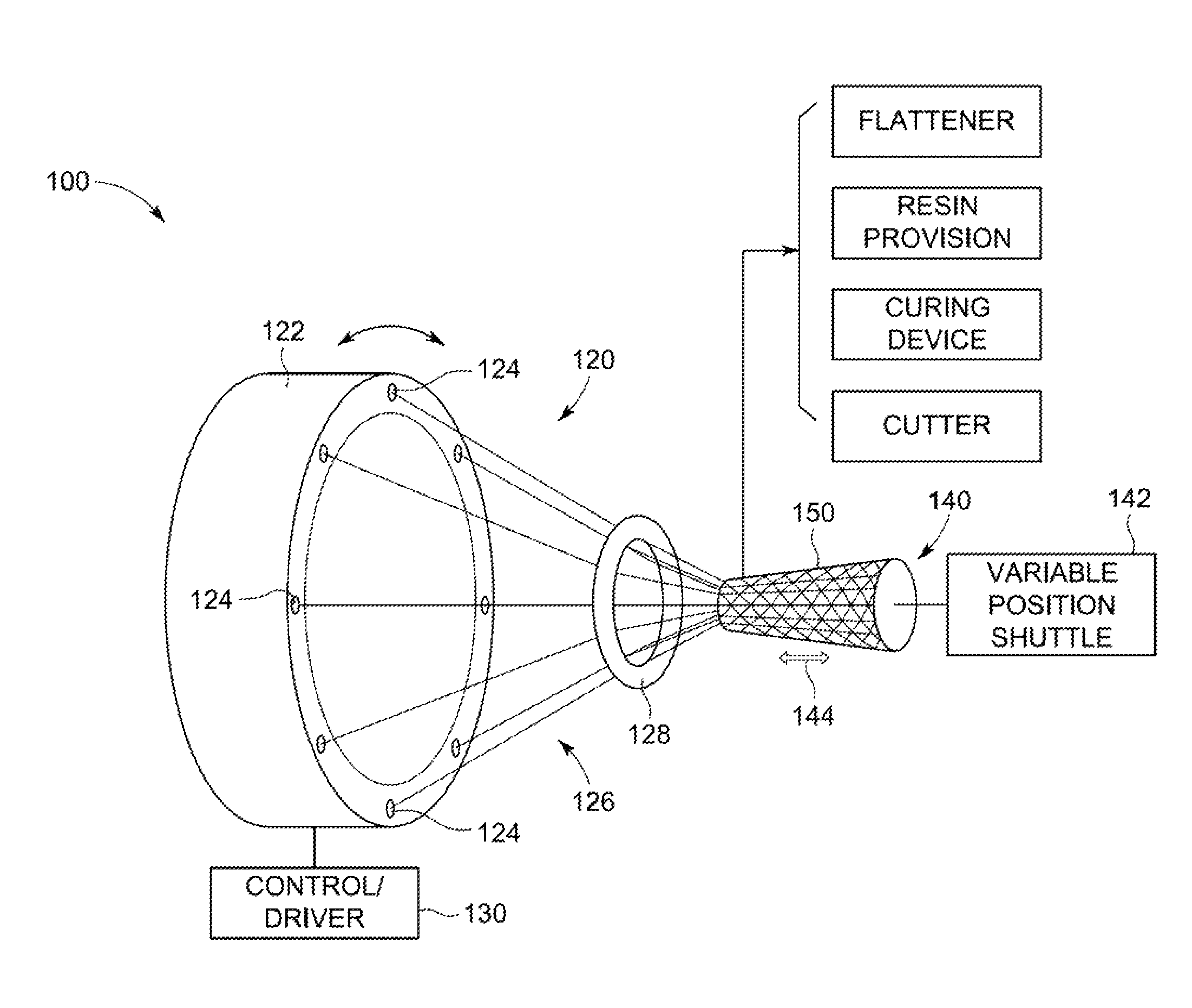
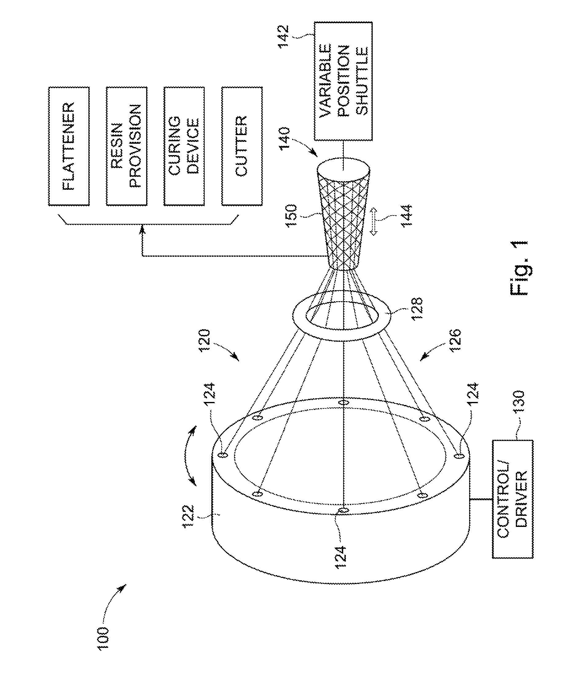
[0022]FIG. 1 shows an apparatus 100 for manufacturing a non-uniform thickness composite spar component 152 in accordance with an embodiment of the present invention. The apparatus comprises a braiding machine 120, a variable position shuttle 142 and a non-cylindrical mandrel 140.

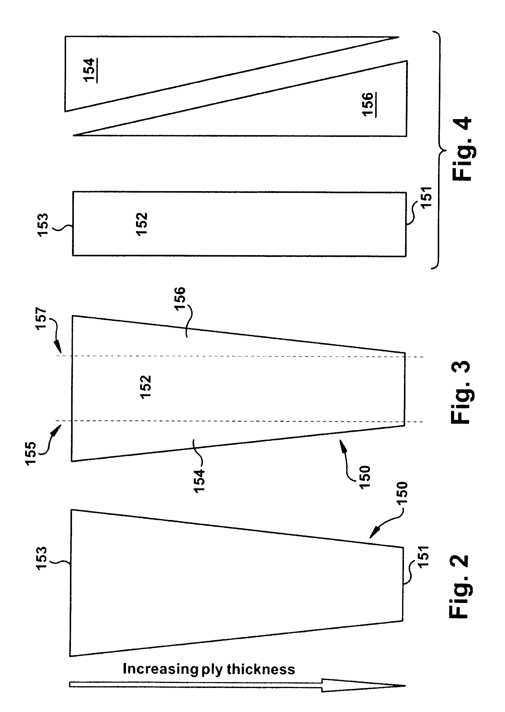
[0023]The non-cylindrical mandrel 140 may be formed of foam, aluminum, plastics, etc., and may be some 1.3 m in length for forming a propeller blade. In various embodiments, a plurality of mandrels (e.g. up to three) of increasing diameter may be used to produce a spar. The variation in thickness of the spar component 152 may be, for example, from about 10 mm to about 15 or 20 mm, and the finished spar component 152 may have dimensions of approximately 1300 mm×250 mm×9 mm, for example.

[0024]In one embodiment, the braiding machine 120 is a Herzog™ RF1 / 192-100 braiding machine available from Herzog Maschinenfabrik GmbH & Co. KG, Am Alexanderhaus 160, D-26127, Oldenburg, Germany [9].

[0025]The braiding machine 1...


PUM

PropertyMeasurementUnit
lengthaaaaaaaaaa
thicknessaaaaaaaaaa
thicknessaaaaaaaaaa

Abstract

According to one aspect, the present invention relates to a method of manufacturing at least one non-uniform thickness composite spar component. The method comprises braiding a plurality of fibers over a non-cylindrical mandrel to form a variable thickness shaped fiber preform, flattening the shaped fiber preform and cutting the flattened shaped fiber preform to obtain the at least one non-uniform thickness composite spar component. Spars made according to various embodiments of the present invention are faster and less expensive to manufacture than conventional composite spar components.

Description

FIELD OF INVENTION[0001]The present invention relates generally to composite spars. More particularly, the present invention relates to composite spars of varying thickness, for example, for use in various aviation applications such as for propeller spars, wing spars, etc.BACKGROUND OF THE INVENTION[0002]A spar is an integral component of many products. Such spars are generally load bearing structural elements used to add support to such products. For example, wing spars are provided in aircraft for fixing the wings to the aircraft and for transmitting lift generated by the wings to the fuselage of the aircraft.[0003]It is known that spars are often formed using metal materials provided either as a solid or in a framework structure. For example, various metal spars are known for use in propeller blades [1-5] to provide structural support to airfoils that are formed thereabouts.[0004]However, spars are sometimes now manufactured using composite materials (e.g. by using woven or braid...

Claims


Application Information

Patent Timeline
Patent Type & Authority Patents(United States)
IPC IPC(8): D04C1/06
CPCB29C70/222B29C70/545Y02T50/433B29L2031/3076B29B11/16B29C53/585D04C1/02D04C3/48D10B2505/02B29C53/68D10B2403/023D10B2403/02411Y02T50/40B29C69/001B29C70/10B29C70/16D04C3/40
Inventor WYBROW, TIM
Owner GE AVIATION SYST LTD
Why Eureka
Try Eureka