Fibre optic duplex connector

a fiber optic and duplex technology, applied in the field of connectors, can solve the problems of complicated process and sticking of parts, and achieve the effect of convenient installation

Inactive Publication Date: 2011-11-22
EUROMICRON WERKZEUGE GMBH
View PDF8 Cites 1 Cited by
  • Summary
  • Abstract
  • Description
  • Claims
  • Application Information

AI Technical Summary

Benefits of technology

[0009]It is therefore an object of the present invention to provide a connector which can be installed more easily.
[0012]The connector housing preferably has two openings as counter holder, into each of which a locking tab engages, wherein the locking tabs are arranged on opposite sides of the connector inner part. The opposing arrangement increases the security and precision of the connection.
[0014]The connector housing preferably comprises at least one means for increasing the deformability of the connector housing when the connector inner part is being inserted, wherein the means for increasing the deformability of the connector housing is preferably a slit introduced from the rear side into at least one of the side walls, preferably both side walls. These measures minimize the force to be applied for the connection and reduce the risk of damage to the housing.

Problems solved by technology

In the case of connectors which have a spring-loaded ferrule, this process is complicated insofar as it can here easily lead to a sticking of the parts that are movable towards each other.

Method used


Image

  • Fibre optic duplex connector
  • Fibre optic duplex connector
  • Fibre optic duplex connector

Examples


Embodiment Construction

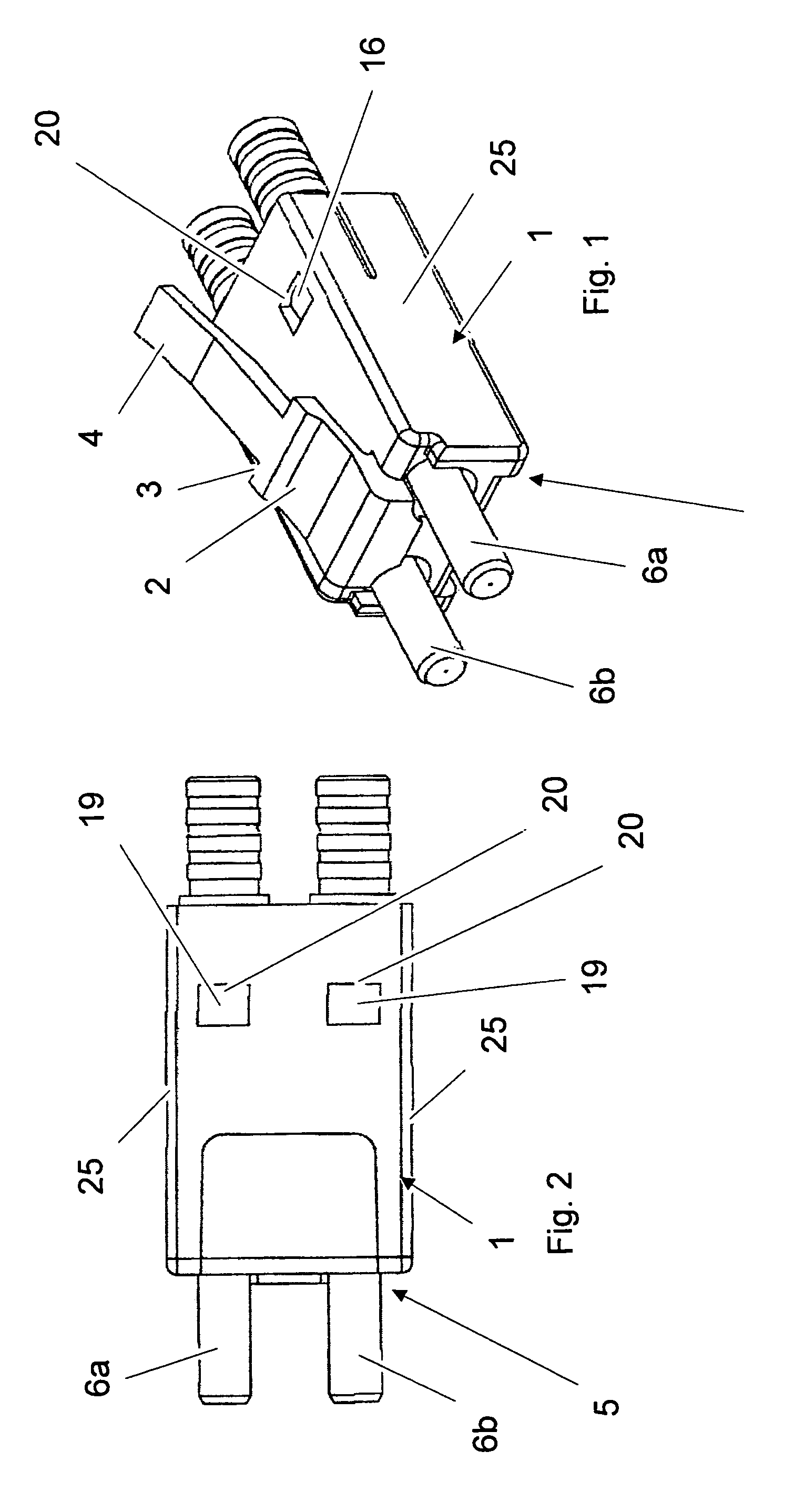
[0021]Reference is first made to FIGS. 1 and 2. These show an embodiment example of a connector according to the invention by means of a connector for two optical fibres. The connector comprises a connector housing 1 which has the dimensions of an R345 connector. The connector housing 1 comprises a locking device 2 with a locking edge 3 which is formed in a spring-elastic manner as a plastic component in the manner of an integral hinge and, with the aid of an actuation bar 4, can be pressed onto the housing in order to unlock a connection with a receptacle. Two ferrules, numbered 6a and 6b, project from the connector housing 1 at one end 5 of the connector housing 1.

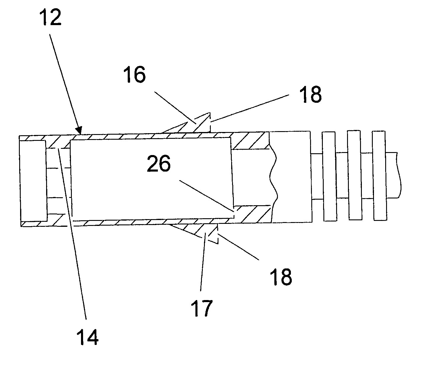
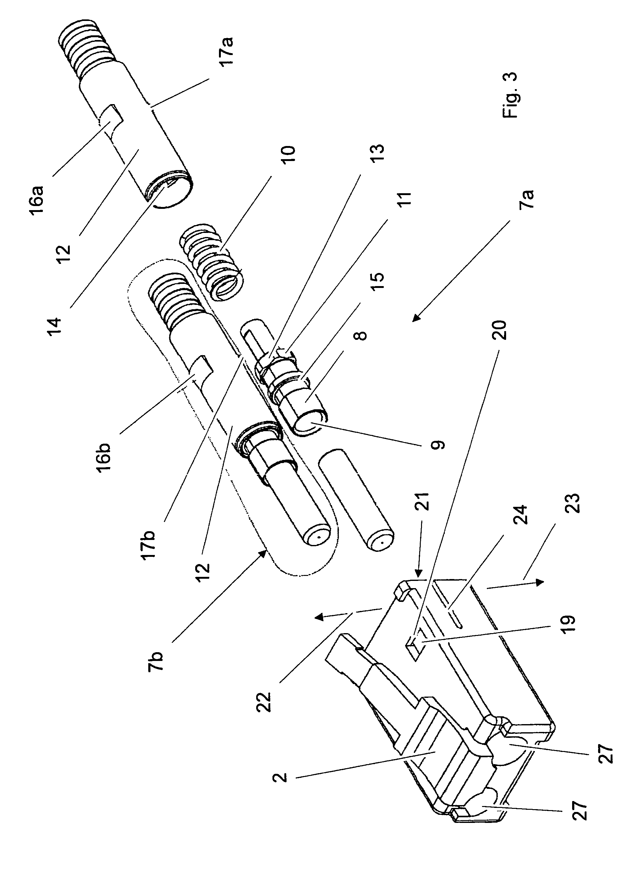
[0022]The ferrules are each part of connector inner parts 7a, 7b, such as are represented for example in FIG. 3. The connector inner parts 7a, 7b are each accommodated in housing openings 27 of the connector housing 1. The connector inner parts 7a, 7b are explained in more detail below using as an example the connector i...


PUM


Abstract

Connector for the termination of optical transmission media including a connector housing and at least one connector inner part arranged therein, which includes a ferrule with a bore for receiving the optical transmission media, wherein the ferrule is arranged in the connector inner part so that it can be moved axially against the force of a spring, wherein the connector inner part is joined to the connector housing by a snap connection, wherein the connector housing has at least one opening into which a locking tab engages when in the installed position, wherein the locking tab is a triangular elevation, extending radially, in longitudinal section in axial direction, on a cylindrical part of the connector inner part.

Description

CROSS REFERENCE TO RELATED APPLICATIONS[0001]This is a National Phase application of PCT application number PCT / EP2008 / 005559, filed Jul. 8, 2008, which claims priority benefit of German application number DE 10 2007 033 246.9, filed Jul. 17, 2007, the content of such applications being incorporated herein by reference.FIELD OF THE INVENTION[0002]The present invention relates to a connector for the termination of optical transmission media.BACKGROUND OF THE INVENTION[0003]To releasably join optical fibres together for example at the back of a device or at a feedthrough through a housing or a wall, connectors and / or receptacles that fit the connectors in the form of individual couplings, called receptacles in the case of optical fibres, are fitted into the ends of the optical fibres to be joined and fixed onto the optical fibres for example by clamping, shrink-fitting, gluing, casting or welding, with the result that light can then be reliably transmitted, by plugging connector and r...

Claims


Application Information

Patent Timeline
Patent Type & Authority Patents(United States)
IPC IPC(8): G02B6/36
CPCG02B6/3869G02B6/3897G02B6/3817G02B6/3833G02B6/3878G02B6/3893
Inventor NEHLER, JURGENWERNER, CHRISTOPH
Owner EUROMICRON WERKZEUGE GMBH
Why Eureka
Try Eureka