Valve

a valve and housing technology, applied in the field of valves, can solve the problems of relatively complex construction of the housing of the type, and achieve the effect of simple construction

Active Publication Date: 2016-10-04
VITESCO TECH GERMANY GMBH
View PDF7 Cites 1 Cited by
  • Summary
  • Abstract
  • Description
  • Claims
  • Application Information

AI Technical Summary

Benefits of technology

[0006]An object of the invention is based on providing a valve which, in particular with regard to the housing, is of simple construction.
[0008]With the arrangement of each flap in a housing part, it is possible for the two individual housings (housing parts) to be of simpler design, whereby they can be produced more easily. Furthermore, the fixtures, such as flap and shaft, can be installed more easily. Here, the additional assembly step for the connection of the two individual housings involves considerably less outlay. A further advantage is that, for the individual housings, use can be made of already existing housings, which is likewise conducive to a simplification of the valve.
[0009]In an advantageous refinement, the two housings are screwed together. In this way, a secure and above all gas-tight connection of the two housings parts is realized. A further advantage is that the flap with the shaft can be installed in each housing in advance, before the two housings are connected to one another.
[0010]In one embodiment, the two housings parts are composed of different materials. The different materials selection permits an optimum adaptation of the respective housing to the field of use. For example, a thermally highly loaded housing, which conducts an exhaust-gas flow may be produced from a metal or a metal alloy, preferably cast aluminum, whereas the less intensely loaded housing may be composed of a plastic. Aside from the lower costs, the lower weight is a major advantage here.

Problems solved by technology

As a result, a housing of said type is of relatively complex construction.

Method used


Image

  • Valve
  • Valve

Examples


Embodiment Construction

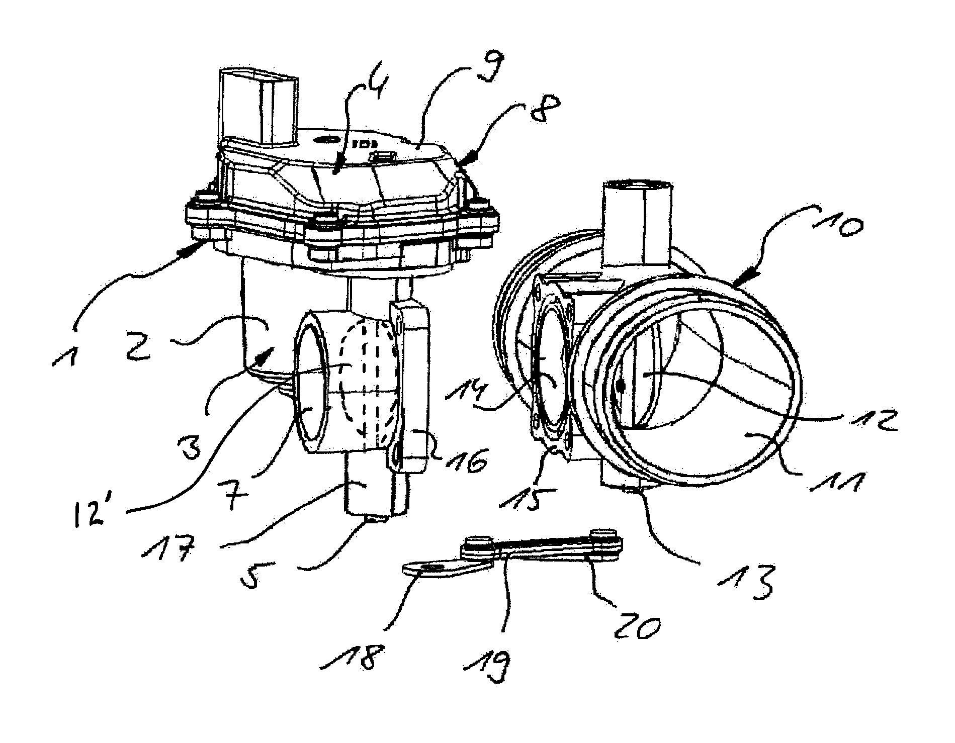
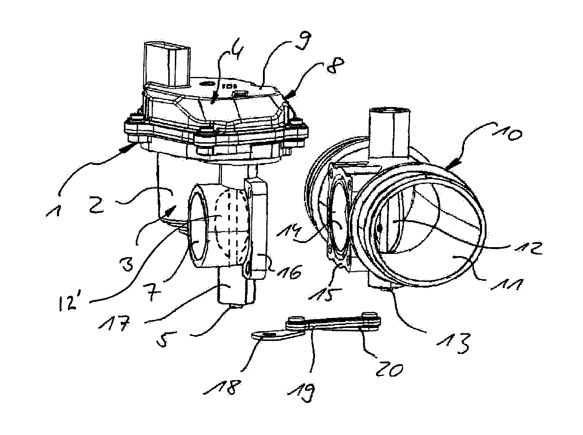
[0015]The valve illustrated in the FIGURE is composed of a first housing 1 with a chamber 2 in which an electric motor 3 is arranged. A shaft 5 is driven by a gearing 4. A first flap 12′ is fastened to the shaft 5, which opens or closes a first duct 7 as a result of a rotation of the shaft 5. The gearing 4 is arranged in a further chamber 8 of the first housing 1, said further chamber being closed off by way of a cover 9. The valve furthermore has a second housing 10 with a second duct 11 in which a second flap 12 is arranged. The second flap 12 is fastened to a second shaft 13, such that the second flap 12 opens or closes the second duct 11 when the second shaft 13 rotates. Downstream of the flap 12 as viewed in the flow direction, the second housing 10 has an opening 14 that issues into the second duct 11, said opening having, on the outer side, a flange 15. The flange 15 is connected to a further flange 16, which is arranged on the end of the first duct 7 of the first housing 1.

[...


PUM


Abstract

A valve for controlling two gas flows, having: two ducts, in each of which a flap is rotatably mounted on a shaft; an electric motor that drives a shaft via a gear unit; and a transmission mechanism which, depending on the movement direction of the first flap, drives the second flap. Each flap is arranged in a separate housing part and the two housing parts are connected to one another.

Description

CROSS REFERENCE TO RELATED APPLICATIONS[0001]This is a U.S. national stage of application No. PCT / EP2013 / 075924, filed on Dec. 9, 2013. Priority is claimed on German Application No. DE102012223466.7 filed Dec. 17, 2012, the content of which is incorporated herein by reference.BACKGROUND OF THE INVENTION[0002]1. Field of the Invention[0003]The invention relates to a valve for regulating two gas flows, wherein, in two ducts, there is arranged a respective flap mounted rotatably on a respective shaft, having an electric motor that drives one shaft via a gearing, and having a transmission mechanism that drives the second flap in a manner dependent on the movement of the first flap.[0004]2. Detailed Description of Prior Art[0005]Valves of this type are used in motor vehicles as air and exhaust-gas valves, and are known. In this case, gas flows pass through the ducts with the flaps, which gas flows are intended to be supplied individually, or mixed in certain ratios, to a third duct in ac...

Claims


Application Information

Patent Timeline
Patent Type & Authority Patents(United States)
IPC IPC(8): F16K11/22F02D9/10F16K31/04F16K27/02F16K11/052
CPCF16K27/0218F02D9/109F16K11/0525F16K31/04Y02T10/121Y10T137/86847F02M26/70F02M26/51Y02T10/12
Inventor GRUNEIS, STEFAN OSKAR
Owner VITESCO TECH GERMANY GMBH
Why Eureka
Try Eureka