Lighting system

a technology of light modules and light beams, applied in the field of light beams, can solve the problems of large dimensions of light beams, and achieve the effect of high operating comfort and immense cost savings

Active Publication Date: 2017-03-21
OASE GMBH
View PDF5 Cites 1 Cited by
  • Summary
  • Abstract
  • Description
  • Claims
  • Application Information

AI Technical Summary

Benefits of technology

[0009]Preferably, the central controller comprises a data bus interface by means of which it is connectable with an electronic data processing device such as a PC, a tablet computer, a smart phone or a compact control unit. In the compact control unit, fixed programs are stored which can be selected, for example, by means of a remote control. In such a case, in particular for an underwater arrangement of the controller, a part of the compact control unit is inconspicuously positionable on a stand, for example, in a flower bed. By means of a remote control, the individual programs can then be selected and retrieved. By means of the data connection, the controller is supplied appropriately with information based on which the light modules with their LED lights can be controlled accordingly. As an alternative or as a supplement, by means of a connection to a PC or another electronic data processing device, a freely programmable control action can be realized in which a user can individually adjust the control action of the light modules. Such an application is, for example, designed as an app for a tablet computer. A compact control unit can also be present in the form of an app on a tablet computer or smart phone in order to enable an operating comfort as high as possible and as modern as possible.
[0010]The advantages of the system according to the invention reside in that only a central controller is required. The individual light modules must therefore contain only possibly present LED drivers or LED power components and do not require their own LED controller. On the one hand, this provides immense cost savings in producing the module and, on the other hand, leads to the already described more compact configuration of the light modules.

Problems solved by technology

Moreover, in particular for wall installations, large dimensions of the light modules are required due to the required mounting space and the dissipation of large heat quantities.

Method used


Image

  • Lighting system
  • Lighting system
  • Lighting system

Examples


Embodiment Construction

[0026]Same or similarly acting parts are provided—inasmuch as useful—with identical reference numbers. Individual technical features of the embodiments described in the following can also lead to further embodiments according to the invention with the features of the afore described embodiments.

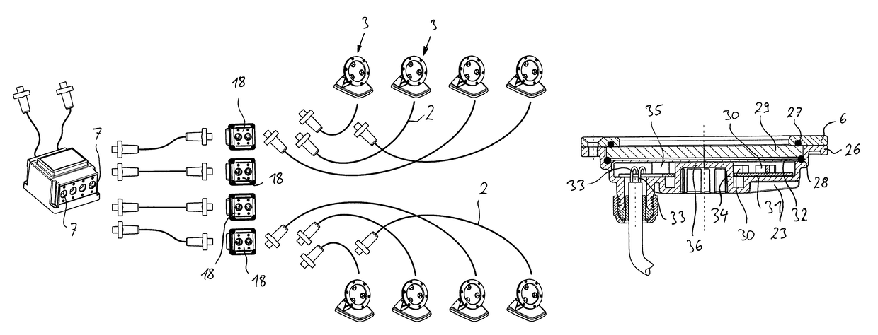
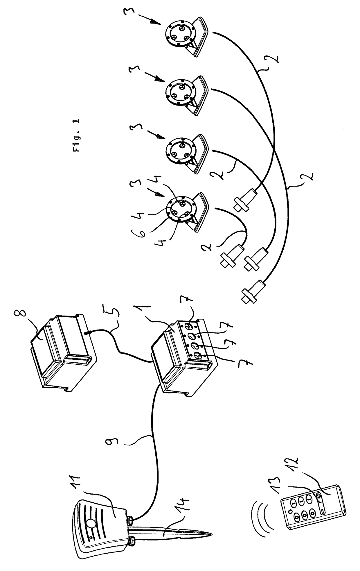
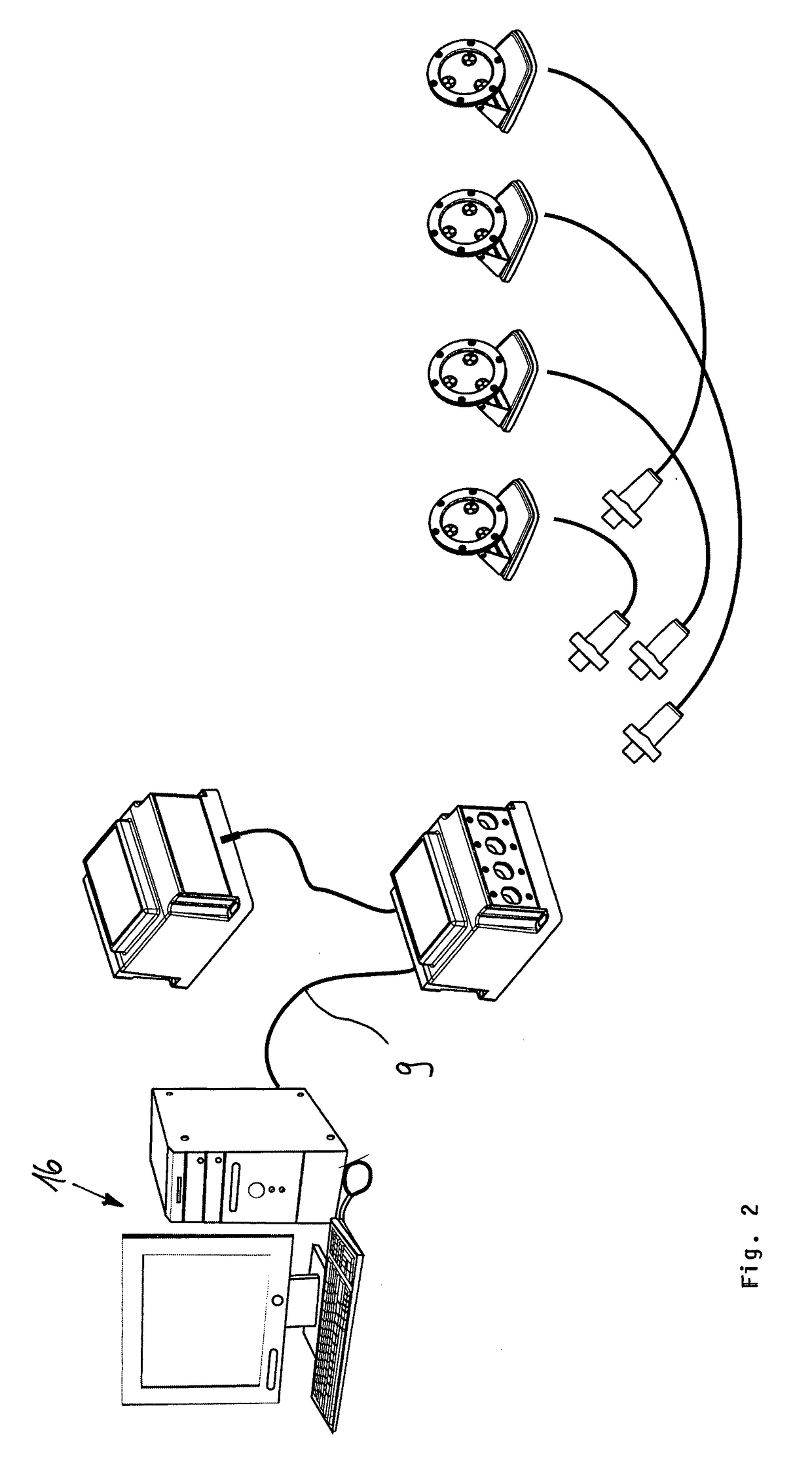
[0027]An article according to the invention according to FIG. 1 comprises a central controller or LED controller 1 that is provided by means of system cables 2 with four light modules 3 in the present case. Each light module 3 comprises three RGB diodes 4 which are uniformly arranged along the circumference of the circular light unit of the light module. Alternatively, instead of an RGB diode, a cluster with at least three diodes of the colors red, green, and blue can be also employed. By means of a screwed-on metal ring 6, a glass pane, not illustrated in detail, is screwed on tightly onto the further housing of the light module for sealing purposes. Each light module 3 has correlated therew...


PUM


Abstract

The invention relates to a lighting system comprising at least one light module (3), preferably a plurality of light modules (3), which can be installed in e.g. pool walls of swimming baths or footpaths and have at least one LED (4), wherein the light modules are each connected by means of at least one system cable (2) to a common central and bus-capable controller (1) and can be controlled thereby, wherein the system cable (2) is provided for power supply to the light modules (3) and for control of the respective light modules (3) from the controller (1), and wherein in each case a light module (3) which can be positioned by means of an associated system cable (2) remote from the controller (1) has a housing, which is in particular watertight, in which driver means are disposed for supplying power to the LED (4).

Description

BACKGROUND OF THE INVENTION[0001]The present invention concerns a lighting system with at least one light module, preferably with a plurality of light modules. The one or more light modules are installable, for example, in the walls of swimming pools (under water) or walkways.[0002]Up to now, the light modules in particular in the underwater area have conventionally always been provided with LEDs that, in addition to the associated power supply and the drivers required for this purpose, comprise a controller at the same time. In operation, the driver means as well as the controller produce heat that must be dissipated. Moreover, in particular for wall installations, large dimensions of the light modules are required due to the required mounting space and the dissipation of large heat quantities.[0003]It is the object of the present invention to design light modules of a lighting system in a more compact configuration.SUMMARY OF THE INVENTION[0004]The object is solved by a lighting s...

Claims


Application Information

Patent Timeline
Patent Type & Authority Patents(United States)
IPC IPC(8): F21V31/00F21V29/00F21V23/04F21V23/02F21V21/30F21S2/00H05B37/02F21V23/00F21V29/507F21W111/023F21W121/02F21W131/401F21Y101/00
CPCF21S2/005F21V21/30F21V23/001F21V23/008F21V23/023F21V23/026F21V23/0435F21V23/009F21K9/20F21V29/507F21V31/00H05B37/0254F21W2111/023F21W2121/02F21W2131/401F21Y2101/00F21Y2113/13F21Y2115/10H05B47/18
Inventor HANKE, ANDREASSCHWINDEN, RAINER
Owner OASE GMBH
Why Eureka
Try Eureka