Linear sensor having angular redirection and cable displacement

a technology of angular redirection and displacement, applied in the field of displacement sensors, can solve the problems of sensor limited space, sensor reliability and/or calibration problems, sensor mounting difficulties, etc., and achieve the effect of facilitating assembly

Inactive Publication Date: 2011-11-22
ROBERT BOSCH GMBH
View PDF6 Cites 3 Cited by
  • Summary
  • Abstract
  • Description
  • Claims
  • Application Information

AI Technical Summary

Benefits of technology

[0015]a magnetic field source integral with said longitudinal element at its upper end, using a so-called second connecting means, so that any displacement of said upper end causes the displacement of said source, said fixed part comprising a receiving means for said magnetic field opposite said source and capable of sending a signal known as the primary signal, depending on said axial path, to a transducer capable of converting said primary signal into an electrical signal S transmitted to a connector, making it possible to transfer said electrical signal S to an external electrical circuit.
[0020]finally, their spatial requirement, which is essentially radial, facilitates their assembly at the junction between said frame and said mobile part.

Problems solved by technology

The displacement sensors of the prior art have several types of problems:firstly, the sensors may have a problem of restricted space, to the extent that they have to be positioned in a relatively small space, in particular in said axial direction corresponding to the direction of displacement of the mobile part sliding in the fixed frame;moreover, the sensors may have problems of reliability and / or of calibration; andfinally, the sensors may present difficulties in terms of mounting, in particular taking into account the restricted access for said mobile part.
More specifically, these problems are posed even more acutely when said sensors have to be installed on braking devices or power-assisted braking devices.

Method used


Image

  • Linear sensor having angular redirection and cable displacement
  • Linear sensor having angular redirection and cable displacement
  • Linear sensor having angular redirection and cable displacement

Examples


Embodiment Construction

[0027]In one advantageous embodiment, said longitudinal element 40 is a flexible longitudinal element 40′, for example a cable, said flexible longitudinal element 40′ extending continuously from said lower end 400 to said upper end 401 over a curvilinear length l>L0.

[0028]Thus, any axial displacement of said lower end 400 of said flexible longitudinal element40′ causes corresponding radial displacement of its so-called upper end 401.

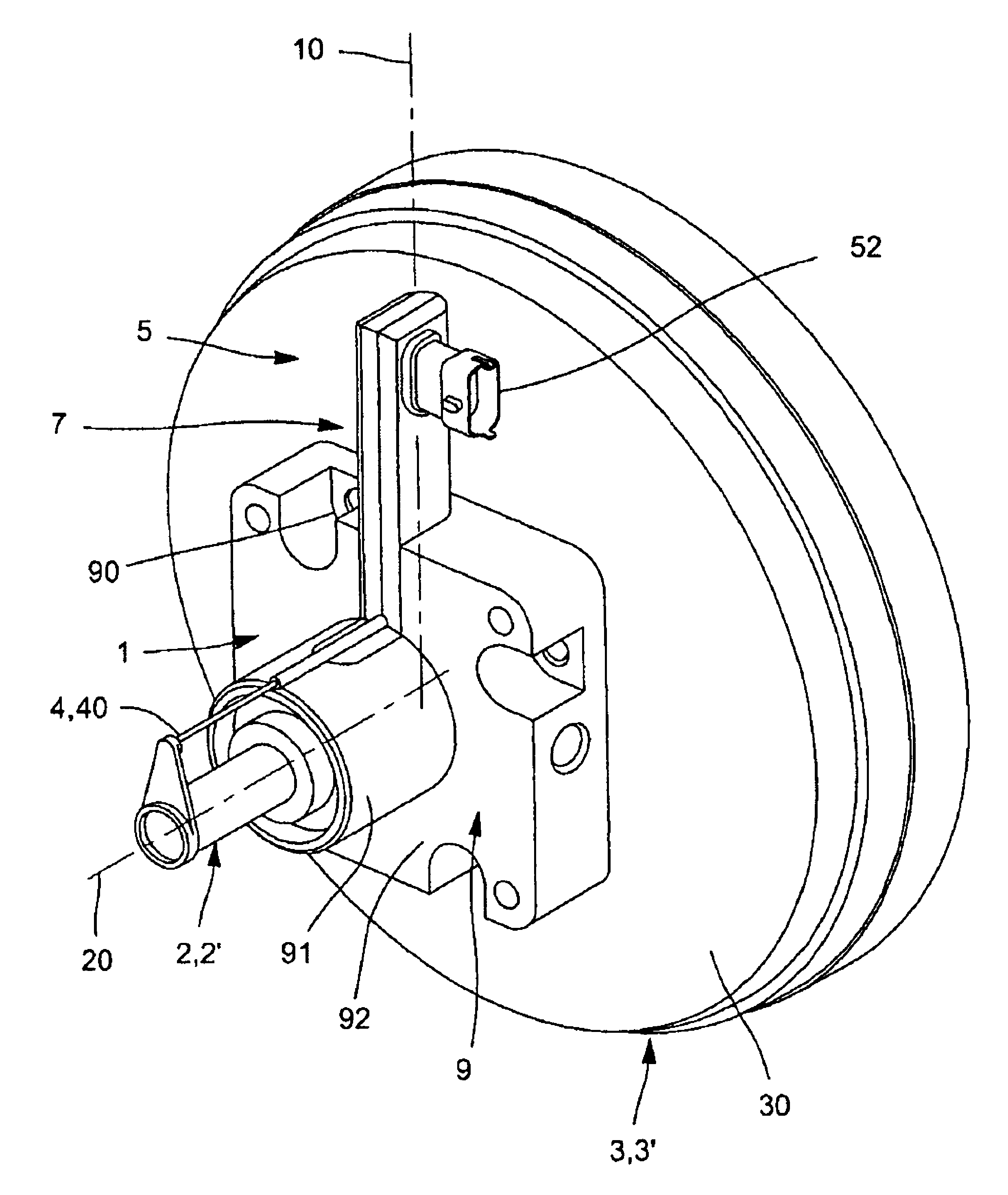
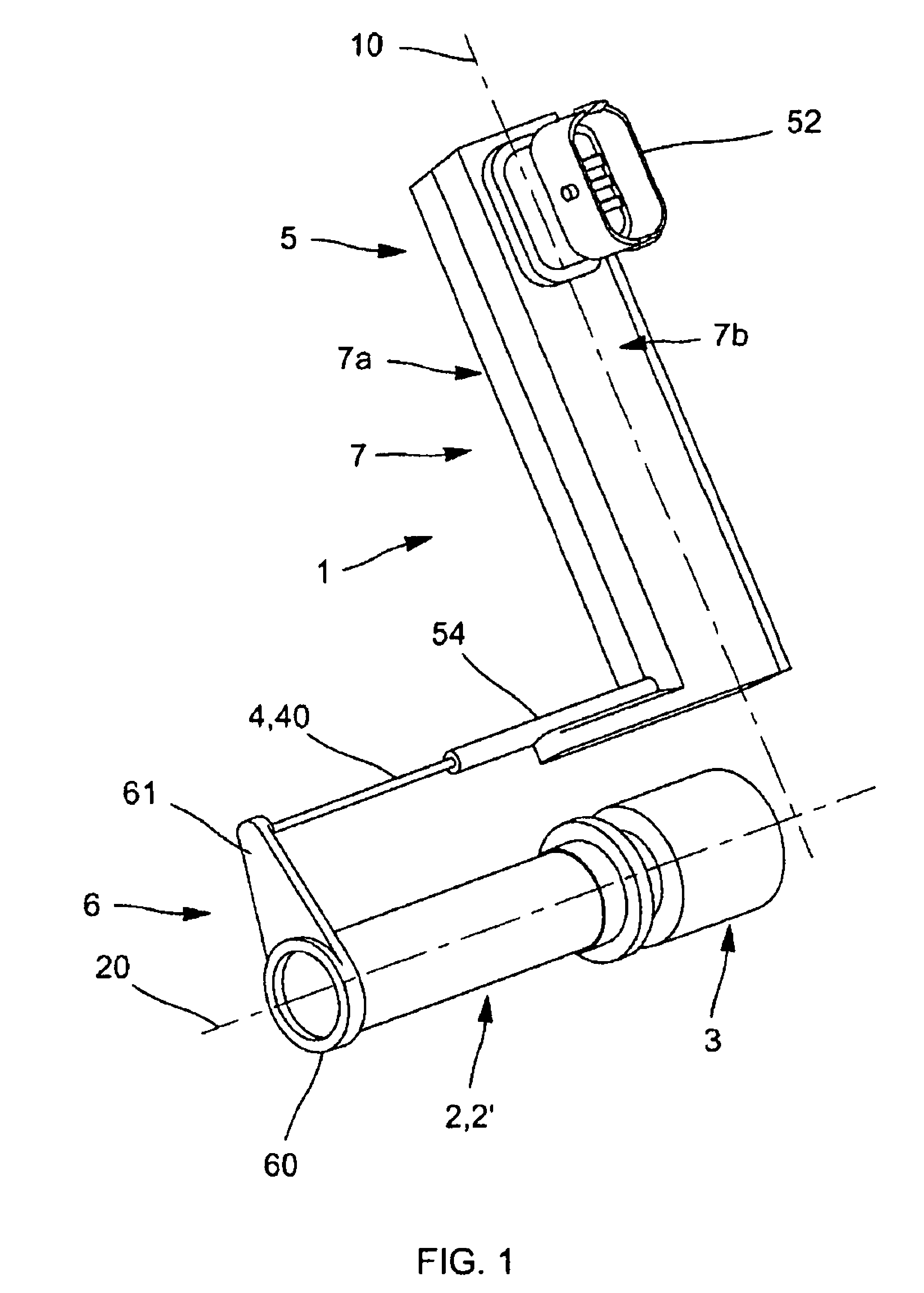
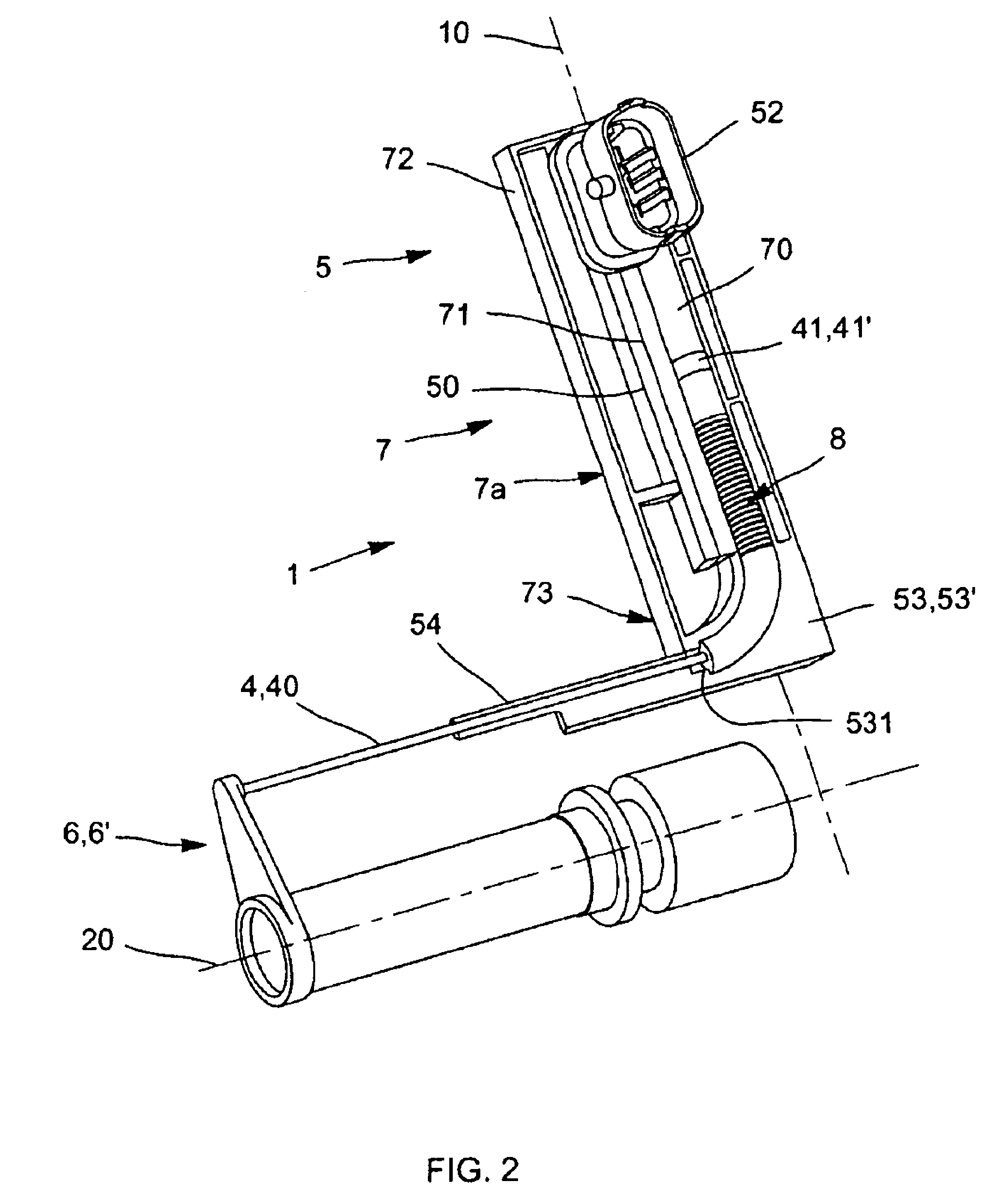
[0029]As illustrated in FIGS. 1 to 3, said angular redirection means 53 is an angular redirection of 90°53′ comprising a cavity, for example a tubular cavity 530 with an average radius of curvature R, forming a guide element angled at 90° for said angled part 402 of said flexible longitudinal element 40′, said tubular cavity 530 having a lower orifice known as the axial orifice 531 and an upper orifice known as the radial orifice 532.

[0030]As illustrated in FIGS. 4a, 4b and 4c, said flexible longitudinal element 40′ has a curvilinear length l at least eq...


PUM


Abstract

The linear sensor 1 for measuring an axial path L0 of a part 2 sliding in an axial direction 20 in a frame 3 comprises a mobile part 4 cooperating with a fixed part 5, said mobile part 4 comprising:a longitudinal element 40 cooperating at one end 400 with said part 2, any translation of said part 2 in said axial path causing a corresponding displacement of its other end 401; and a magnetic field source 41 integral with the end 401, said fixed part 5 comprising a receiving means 50 for said magnetic field. The linear sensor is characterized in that said fixed part 5 comprises an angular redirection means 53 cooperating with said longitudinal element 40 and thus transforming said axial path of the end 400 into a radial path of the other end 401.

Description

BACKGROUND AND SUMMARY OF THE INVENTION[0001]The invention relates to the field of displacement sensors and, more specifically, displacement sensors used in motor vehicle devices or equipment, for example in braking devices or power-assisted braking devices.[0002]Displacement sensors are already well known in principle. Said linear sensors, for measuring an axial path of a part sliding in an axial direction in a frame, comprise a so-called mobile part cooperating with a so-called fixed part. Said mobile part of the sensor comprises:[0003]a longitudinal element cooperating with said part so that any translation of said part causes an axial translation of said mobile part; and[0004]a magnetic field source integral with said longitudinal element at its end so that any displacement of said upper end causes the displacement of said source.[0005]Said fixed part comprises a receiving means for said magnetic field arranged opposite said source and capable of sending a signal known as the pr...

Claims


Application Information

Patent Timeline
Patent Type & Authority Patents(United States)
IPC IPC(8): G01B7/14G01B7/30G01R33/06H01L43/06
CPCB60T7/042B60T13/52B60T13/57F15B15/2861G01D5/12G01D11/245F15B15/2853F15B15/2892
Inventor CAGNAC, BASTIENFOURCADE, JEAN
Owner ROBERT BOSCH GMBH
Why Eureka
Try Eureka