Molding material transfer method and substrate structure

a technology of material transfer and substrate, which is applied in the manufacture of electrode systems, electrical discharge tubes/lamps, and address electrodes. it can solve the problems of bubble defects, defects in the ribs (underfilled parts), and bubble defects, and achieve high reliability

Inactive Publication Date: 2009-05-12
HITACHI PLASMA PATENT LICENSING +1
View PDF14 Cites 2 Cited by
  • Summary
  • Abstract
  • Description
  • Claims
  • Application Information

AI Technical Summary

Benefits of technology

[0017]According to the above mentioned aspects of the present invention, a new and highly reliable technology for manufacturing a substrate with a protrusion pattern can be provided. The structural defects caused by the involvement of bubbles during the formation of the protrusion pattern can be decreased considerably, and the reliability of the product and the yield of the product can be improved. Since offline steps such as vacuum deaeration are unnecessary, the production efficiency can be improved and the processing steps can be simplified.
[0020]According to the present invention, a new and highly reliable technology for manufacturing the substrate with a protrusion pattern can be provided. In addition to this, using the present invention has an effect that transfer of a material is possible without allowing the material to be transferred to attach to portions other than the grooves of the concave portion for filling or the grooves of the concave portion for transfer.

Problems solved by technology

A problem of filling the molding material into the intaglio plate for transfer is that bubbles may enter the grooves for filling the molding material on the intaglio plate for transfer.
As a result, the molding material is not filled into that part of the grooves, which may cause defects in the ribs (underfilled parts) after the transfer.
This problem occurs because the bubbles entrain when the molding material is being filled into the grooves.
If the groove pattern of the intaglio plate for transfer is linear, and the molding material extends in the filling direction, or if the direction of the bubbles to escape is uniquely determined, when squeezing is performed for example, then the probability of the bubbles to remain is decreased by sequentially filling the molding material so as to push out the bubbles sequentially from the edge of the intaglio plate for transfer, but in the case of grooves being crossed such as the case of a lattice pattern, the bubbles which entrained cannot escape anywhere at the intersections, and often end up as bubble defects.
A possible method is pushing out the bubbles by repeatedly squeezing many times, but this is not efficient.
Also if the intaglio plate for transfer is made of a material that can be easily deformed, such as a silicone resin, then the intaglio plate for transfer itself may be damaged by the squeezing.
This method, however, is very inefficient.
This method utilizes a phenomenon that the molding material wets the wall face of grooves of the intaglio plate for transfer, but for this, it is considered that the supply amount of the molding material to the intaglio plate for transfer must be extremely small, and a method for controlling this at the industrial level has not yet been developed.
Also in this method, the molding material is filled such that the molding material is sandwiched between the substrate and the intaglio plate for transfer, so it is extremely difficult to accurately control the film thickness of the dielectric layer in the case in which the dielectric layer and the ribs for the PDP are simultaneously formed.

Method used


Image

  • Molding material transfer method and substrate structure
  • Molding material transfer method and substrate structure
  • Molding material transfer method and substrate structure

Examples


example 1

[0088]In this example, the principle of the present invention will be described with reference to FIG. 12 to FIG. 16. FIG. 12 is a schematic plan view depicting the concave portions 111 of the intaglio plate for filling. FIG. 13 is a schematic side cross-sectional view thereof, FIG. 14 is a schematic plan view depicting the grooves 141 of the intaglio plate for transfer, FIG. 15 is a schematic side cross-sectional view thereof, and FIG. 16 is a schematic side cross-sectional view depicting a status where the concave portions 111 of the intaglio plate for filling and the grooves 141 of the intaglio plate for transfer are met. In FIG. 12 to FIG. 16, the groove patterns formed on the intaglio plate for filling and the intaglio plate for transfer are both lattices, and these shapes overlap with each other when the intaglio plate for filling and the intaglio plate for transfer are superimposed. The dimensions in FIG. 12 and the dimensions in FIG. 14 are in a 1:1 relationship, and as a co...

example 2

[0091]In this example, a molding material transfer apparatus and a substrate manufacturing apparatus in the case where the intaglio plate for filling is in the shape of a plane and the intaglio plate for transfer is bendable into be a cylindrical plane, and how to use these apparatuses, will be described.

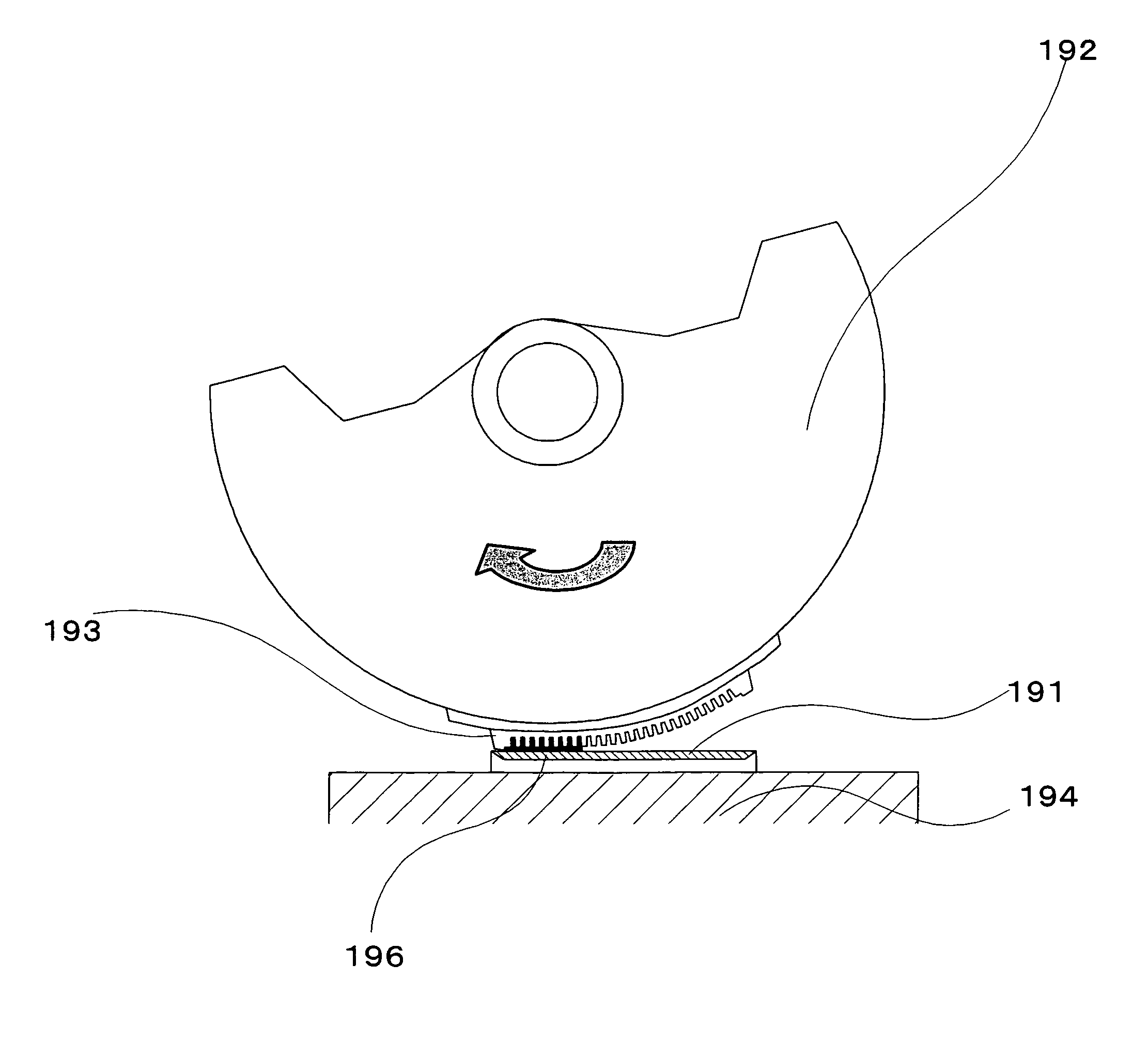
[0092]FIG. 19 shows a status where a molding material is being filled from an intaglio plate for filling 191 placed on a flat table 194 into an intaglio plate for transfer 193 installed on a plate cylinder 192 which is in the shape of a cylindrical plane. In the grooves of the intaglio plate for filling 191, the molding material has been filled in advance. As the plate cylinder 192 rotates in the arrow direction, the intaglio plate for transfer 193 and the intaglio plate for filling 191 are partially contacted, the molding material shifts from the grooves of the intaglio plate for filling 191 to the grooves of the intaglio plate for transfer 193 by the capillary phenomenon, and the ...

example 3

[0095]In this example, a molding material transfer apparatus and a substrate manufacturing apparatus, in the case where an intaglio plate for filling is a plane and an intaglio plate for transfer is bendable, and how to uses these apparatuses, will be described.

[0096]First according to step S221 in FIG. 22, a molding material is filled into an intaglio plate for filling 191 by squeezing as shown in FIG. 23A.

[0097]Then according to step S222 in FIG. 22, an intaglio plate for transfer 193 is set facing the intaglio plate for filling 191 as shown in FIG. 23B.

[0098]Then according to step S223 in FIG. 22, the intaglio plate for transfer 193 is bent using a roller 231 as shown in FIG. 23C, so that the intaglio plate for filling 191 and the intaglio plate for transfer 193 are partially contacted, and the molding material is shifted from the grooves of the intaglio plate for filling 191 to the grooves of the intaglio plate for transfer 193 by the capillary phenomenon, and the grooves of the...


PUM


Abstract

The present invention provides a new and highly reliable substrate manufacturing technology for manufacturing a substrate with a protrusion pattern, which can decrease structural defects caused by involving bubbles when the protrusion pattern is formed, can improve the reliability of the product and the yield of the product, does not require off-line steps such as vacuum deaeration, and therefore improves the production efficiency and simplifies the steps. According to the present invention, a molding material paste is filled into the concave portions of an intaglio plate for filling, an intaglio plate for transfer on which a specific groove pattern is formed is partially contacted with the intaglio plate for filling, the molding material is filled into the grooves of the intaglio plate for transfer, then the molding material is transferred from the intaglio plate for transfer to a substrate as a protrusion pattern.

Description

CROSS-REFERENCE TO RELATED APPLICATIONS[0001]This application is based upon and claims the benefit of priority from the prior Japanese Patent Application No. 2004-221030, filed on Jul. 29, 2004, the entire contents of which are incorporated herein by reference.BACKGROUND OF THE INVENTION[0002]1. Field of the Invention[0003]The present invention relates to a technology for forming a protrusion pattern such as ribs on a substrate with ribs (barriers) to be used for a plasma display panel (PDP), for example.[0004]2. Description of the Related Art[0005]As an example of the case where a substrate with a protrusion pattern is required, a PDP will be described. A PDP is a self light emitting display panel where a pair of substrates (normally glass substrates) are disposed facing each other with a small space in between, and a discharge space is created inside by sealing the periphery thereof.[0006]Generally in a PDP, ribs (protrusions) with a 150-250 μm height are formed in a repeated mann...

Claims


Application Information

Patent Timeline
Patent Type & Authority Patents(United States)
IPC IPC(8): B41M1/10B41F17/14H01J9/02H01J11/12H01J11/22H01J11/24H01J11/26H01J11/34H01J11/36
CPCB41M1/10B41M3/006H01J11/36
Inventor TOYODA, OSAMUINOUE, KAZUNORITOKAI, AKIRA
Owner HITACHI PLASMA PATENT LICENSING
Why Eureka
Try Eureka