
Method and apparatus for monitoring the maximum distance between two objects

a maximum distance and object technology, applied in power management, modulation, transmission, etc., can solve the problem that the evaluation of the strength of the reception field does not allow detection, and achieve the effect of high user acceptan

Inactive Publication Date: 2011-11-22
MISSION CONTROL DESIGN
View PDF11 Cites 6 Cited by
  • Summary
  • Abstract
  • Description
  • Claims
  • Application Information

AI Technical Summary

Benefits of technology

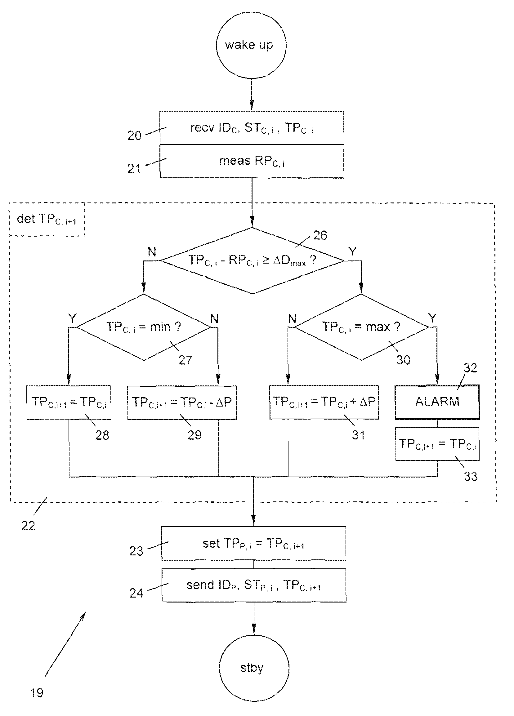
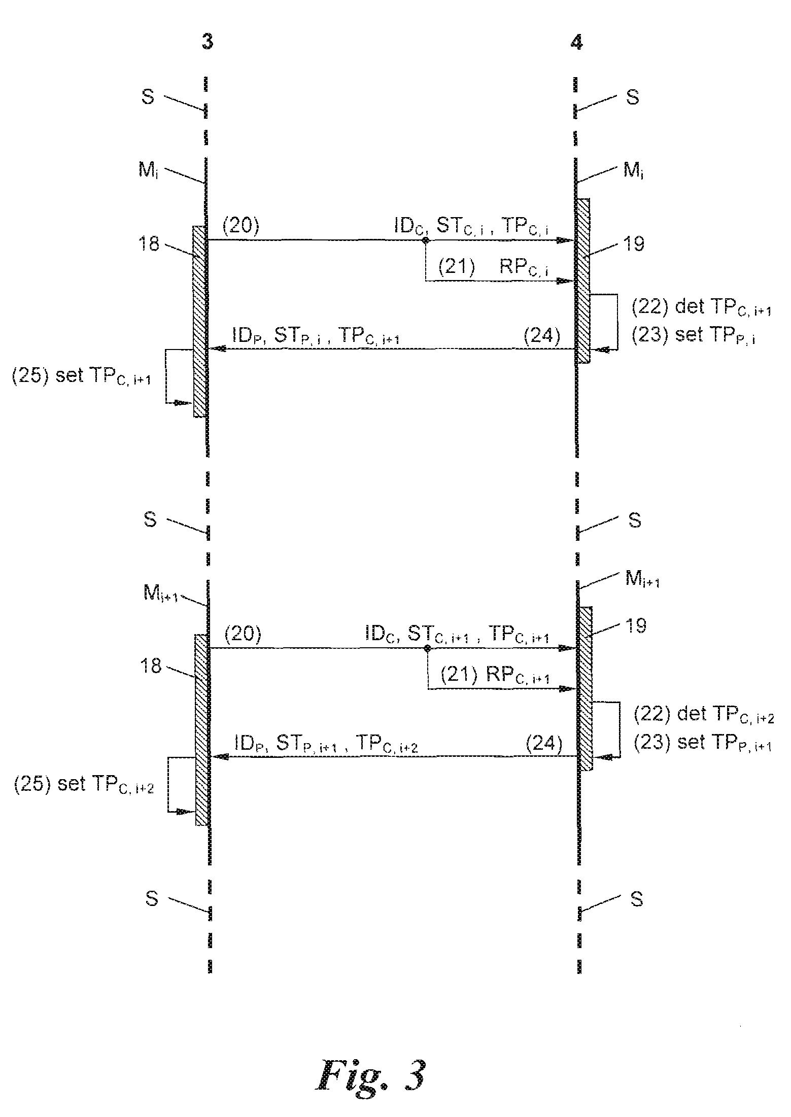
[0006]Through the comparison according to the invention of the reception power with the transmission power specified in the status message itself, the actual attenuation of the transmission channel is measured, even when, e.g., the child station has responded with low transmission power. Therefore, an especially reliable power regulation and effective reduction of the average transmission power is possible. The transmission power of the transceiver transmitting the status messages is adapted with each communications cycle to the actual requirements and prepared for the next communications cycle. The solution according to the invention requires, in each communications cycle, only a single message exchange between the transceivers, namely a single status message and a single confirmation message. Therefore, a very low average energy consumption is achieved, without endangering the reliability of the distance monitoring.
[0007]According to one preferred embodiment of the invention, the transmission power determined for the next status message is also used for the transmission of the confirmation message itself, by means of which the energy consumption is reduced even more.
[0008]Another preferred configuration of the method of the invention distinguishes itself in that, for the mentioned comparison, a difference is formed from the specified transmission power and measured reception power and compared with a threshold, and when the difference falls below the threshold, the transmission power to be used for the next status message is reduced to a minimum value, while when the difference exceeds the threshold, it is increased up to a maximum value, wherein in the latter case, an alarm is triggered if the specified transmission power already has the maximum value. The comparison, by forming a difference, permits an especially simple implementation of the method with economical 1-chip microcontrollers, which allows miniaturization of the transceivers.
[0009]It is especially advantageous when the transceivers move into an energy-saving sleep mode in a known way during the pauses of their periodic message exchange. The second transceiver is woken from this sleep mode before the first transceiver. In this way, a lower energy consumption is achieved, without there being the risk that the second transceiver misses a status message.
[0018]Preferably, the transceivers are configured in the shape of armbands. This allows an uncomplicated and comfortable use and thus guarantees high user acceptance.

Problems solved by technology

The principle of such a reception field strength evaluation does not allow detecting whether a weak reception field strength is to be traced to low transmission power or to a large distance.

Method used


Image

  • Method and apparatus for monitoring the maximum distance between two objects
  • Method and apparatus for monitoring the maximum distance between two objects
  • Method and apparatus for monitoring the maximum distance between two objects

Examples


Embodiment Construction

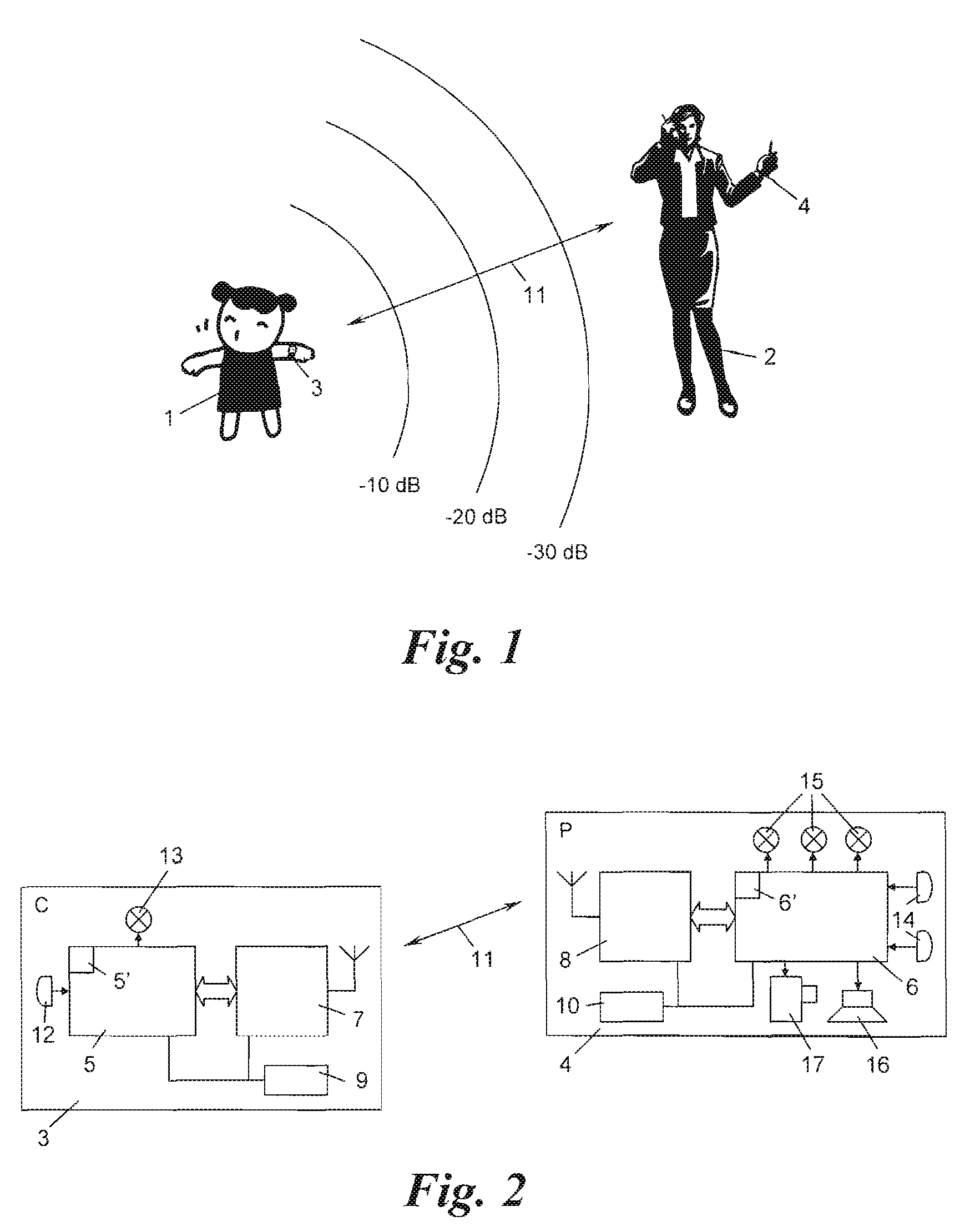
[0024]According to FIGS. 1 and 2, a device for monitoring the maximum distance between two objects, e.g., a child 1 by its guardian 2, comprises two transceivers 3, 4 that are configured in the form of armbands and worn by the child 1 and the guardian 2, respectively.

[0025]Each transceiver 3, 4 comprises a microcontroller 5, 6 with a bidirectional high-frequency transceiver 7, 8 connected to the respective microcontroller. These components are powered by a power supply 9, 10, e.g., a button battery. By means of the transceivers 7, 8, the transceivers 3, 4 are in communications connection with each other via a transmission channel 11.

[0026]The first transceiver 3 has a button 12 for selecting operating states and an LED 13 for displaying the same; in the same way, the second transceiver 4 is equipped with a keypad 14 in the form of two buttons for selecting operating states and a display device 15 in the form of several LED's for displaying the operating states. The second transceive...


PUM


Abstract

A method and an apparatus for monitoring the maximum distance between two objects, in particular between a child and its guardian, with the aid of two transceivers, the first of which periodically transmits status messages of a particular transmission power to the second, wherein an alarm is triggered in the second transceiver if the reception of the status messages decrease, and wherein a statement of the transmission power is concomitantly transmitted in each status message, are distinguished by the fact that the transmission power to be used for the next status message is determined by comparing the reception power with the transmission power stated in a status message and is transmitted back to the first transceiver in a confirmation message.

Description

[0001]This application claims priority based on an International Application filed under the Patent Cooperation Treaty, PCT / AT2007 / 000187, filed on Apr. 24, 2007 and Austrian Application No. A 696 / 2006, filed on Apr. 25, 2006.BACKGROUND OF THE INVENTION[0002]The present invention relates to a method and device for monitoring the maximum distance between two objects, in particular, between a child and its guardian, with the help of two transceivers, of which the first periodically transmits status messages of a certain transmission power to the second, wherein an alarm is triggered in the second transceiver when the reception of the status messages decreases, and wherein information on the transmission power is also transmitted in each status message.[0003]A method and a device of this type are known from U.S. Pat. No. 5,963,130. Because the communications between the transceivers is limited to periodic messages with intermediate pauses, energy consumption reduces. U.S. Pat. No. 5,96...

Claims


Application Information

Patent Timeline
IPC IPC(8): G08B1/08H04B1/16H04B7/00H04W24/00H04B17/00G08B17/10
CPCG08B21/0222G08B21/023G08B21/0247G08B21/025H04B17/318H04B17/23H04W52/228H04W52/283H04B17/24
Inventor KAUFMANN, HANNES
Owner MISSION CONTROL DESIGN
Learn More