Scalable Wind Power Station

a wind power station and scalable technology, applied in solar heat collectors for particular environments, dynamo-electric machines, sustainable buildings, etc., can solve the problems of considerable attack surface of the turbine, and achieve the effect of efficient catching the wind and maximising the energy yield

Active Publication Date: 2021-07-08
RAKOCZI VIKTOR
View PDF0 Cites 2 Cited by
  • Summary
  • Abstract
  • Description
  • Claims
  • Application Information

AI Technical Summary

Benefits of technology

[0026]The method may also include a step of moving the second screen such that the turbine efficiently catches the wind. A gap between the two screens may be controlled such that wind is caught well by the turbine.
[0027]In another preferred embodiment of the method, a solar irradiation is determined and the first and/or second screens are moved such that wind to or from the turbine is blocked in all radial directions and the turbine is controlled to be propelled by v...

Problems solved by technology

The building may disturb the air flow of natural wind and focus it.
An at...

Method used


Image

  • Scalable Wind Power Station
  • Scalable Wind Power Station
  • Scalable Wind Power Station

Examples


Embodiment Construction

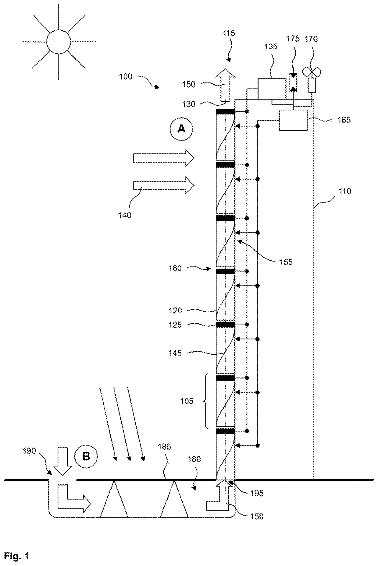
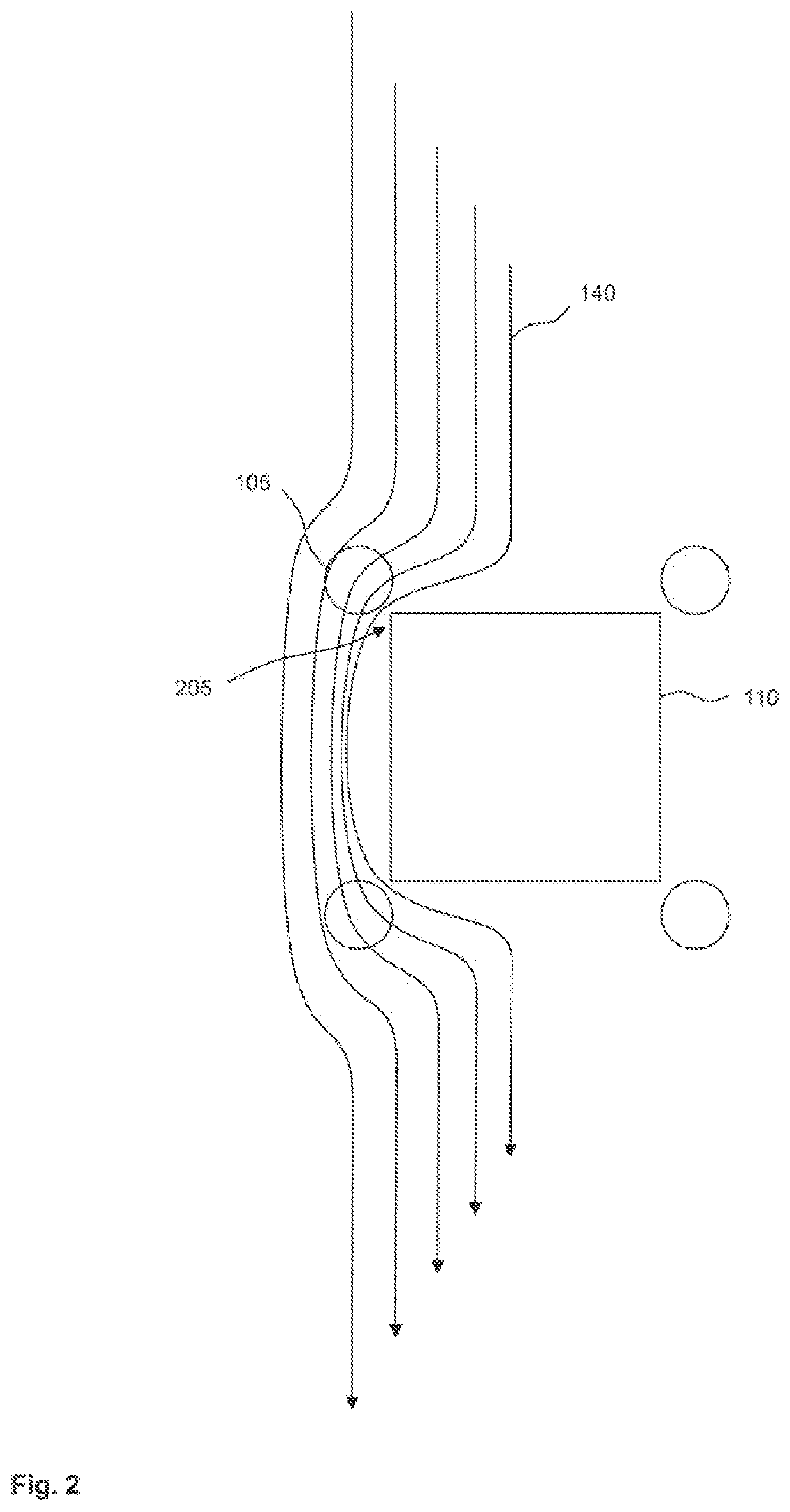
[0035]FIG. 1 shows a system 100 for harvesting wind energy. The system 100 includes one or more turbine assemblies 105 which are attached to a building 110, preferably at a corner thereof. Several turbine assemblies 105 may be stacked into one column 115. In the column 115 adjacent turbine assemblies 105 may be disposed along a straight line and in relative proximity vertically, allowing air to flow vertically through the turbine assemblies 105.

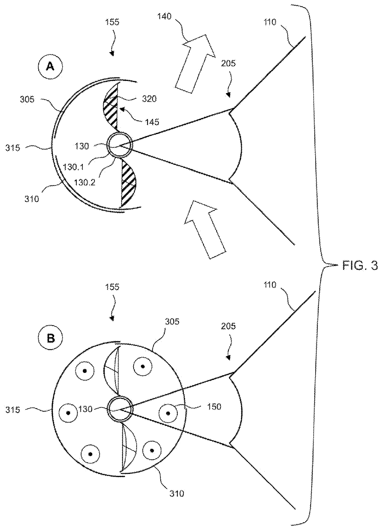
[0036]A turbine assembly 105 includes a turbine 120 and an electric generator 125 mechanically coupled therewith. The turbine 120 has a vertical axis 130 of rotation and is adapted to convert air movement into rotational energy. The generator 125 is adapted to generate electrical power from rotational energy of the wind turbine 120 and is preferred to include a three-phase brushless electric generator. A number of pole pairs of the generator 125 may be adapted to expected rotational speeds of the turbine and a desired frequency of a generated...


PUM


Abstract

A system includes a wind turbine with a vertical axis of rotation; and an electric generator that is configured to generate electrical power from rotational energy of the wind turbine. The wind turbine is adapted to be mounted along of a vertical corner of a building.

Description

CROSS REFERENCE TO RELATED APPLICATION[0001]This application claims priority of German patent application no. 10 2020 000 063.0, filed Jan. 8, 2020, the entire content of which is incorporated herein by reference.FIELD OF THE INVENTION[0002]The present disclosure concerns the generation of electric energy. Specifically, the disclosure concerns an electrical power station for a building.BACKGROUND OF THE INVENTION[0003]A modern commercial building may have significant demands for electric power. Power may be drawn from an electrical power grid which is traditionally fed by one or more centralized power generators. Sometimes an electric power grid is not reliable or power that can be drawn from it may be limited. The building can be made more self-sufficient by equipping it with a local power generator, such as a photovoltaic solar system or a wind turbine.[0004]A solar system may suffer from low efficiency in elevated temperatures or if a solar collector is not pointed directly at th...

Claims


Application Information

Patent Timeline
IPC IPC(8): F03D3/00F03D9/25F03D3/02F03D9/45H02K7/18F24S20/60
CPCF03D3/005F03D9/25F03D3/02F05B2220/708H02K7/183F24S20/60F05B2220/706F03D9/45F05B2240/9112F05B2240/213F05B2260/24H02K2213/03F24S20/61F24S20/64Y02E10/74Y02E10/728Y02E10/46Y02B10/20Y02B10/30
Inventor RAKOCZI, VIKTOR
Owner RAKOCZI VIKTOR
Why Eureka
Try Eureka