Method and system for adaptive direct volume rendering

Active Publication Date: 2006-12-07
FOVIA
View PDF10 Cites 80 Cited by
  • Summary
  • Abstract
  • Description
  • Claims
  • Application Information

AI Technical Summary

Benefits of technology

[0011] A preferred embodiment of the present invention is an adaptive direct volume rendering method and system that generate high-quality

Problems solved by technology

Going back to the CT example discussed above, even though a doctor can arbitrarily generate 2-D image slices of the heart by intercepting the image volume in any direction, no single image slice is able to visualize the whole surface of the heart.
First, direct volume rendering is a computationally expensive process.
However, many of these algorithms achieve their efficiency by sacrifici

Method used


Image

  • Method and system for adaptive direct volume rendering
  • Method and system for adaptive direct volume rendering
  • Method and system for adaptive direct volume rendering

Examples


Embodiment Construction

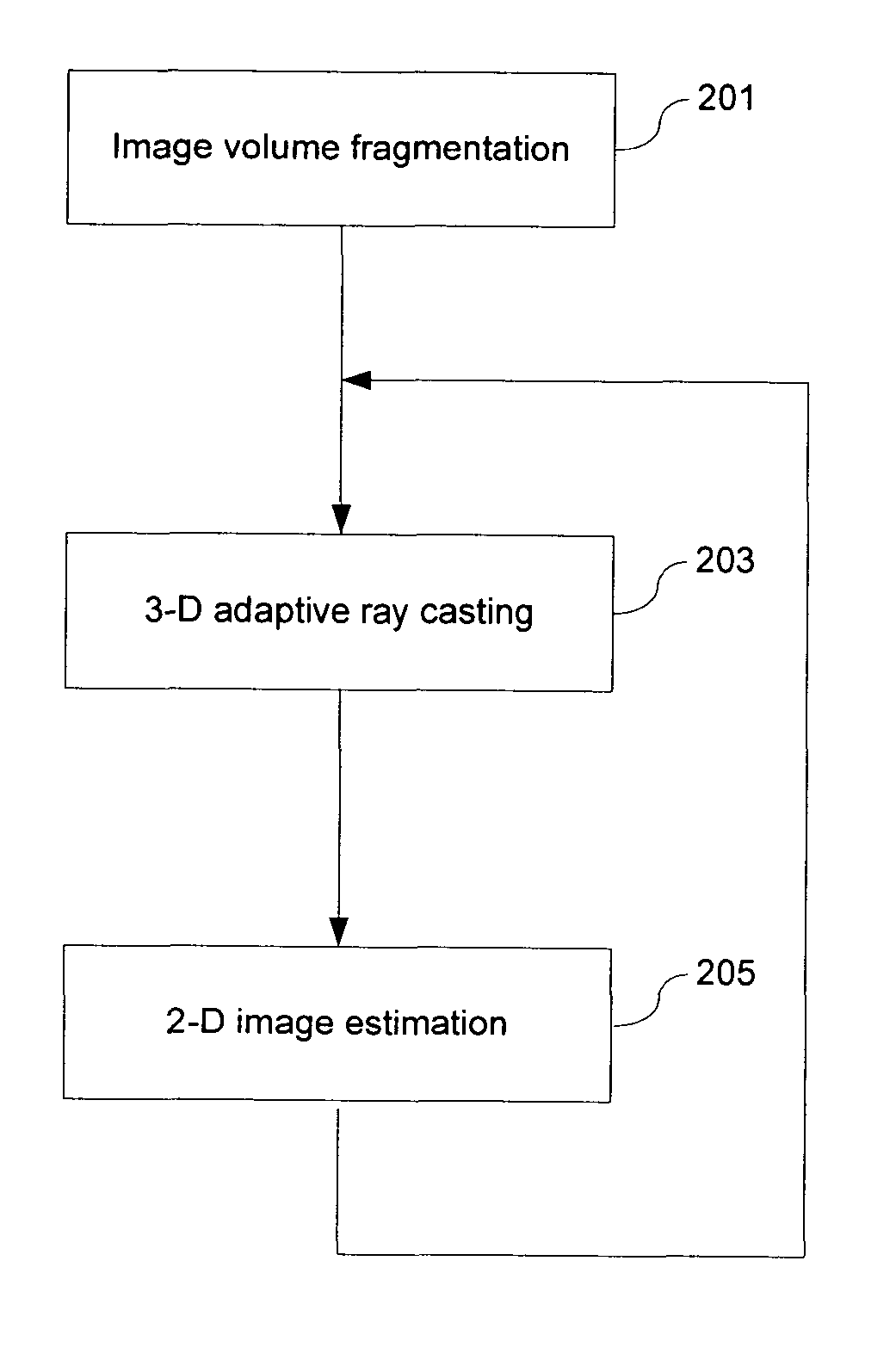
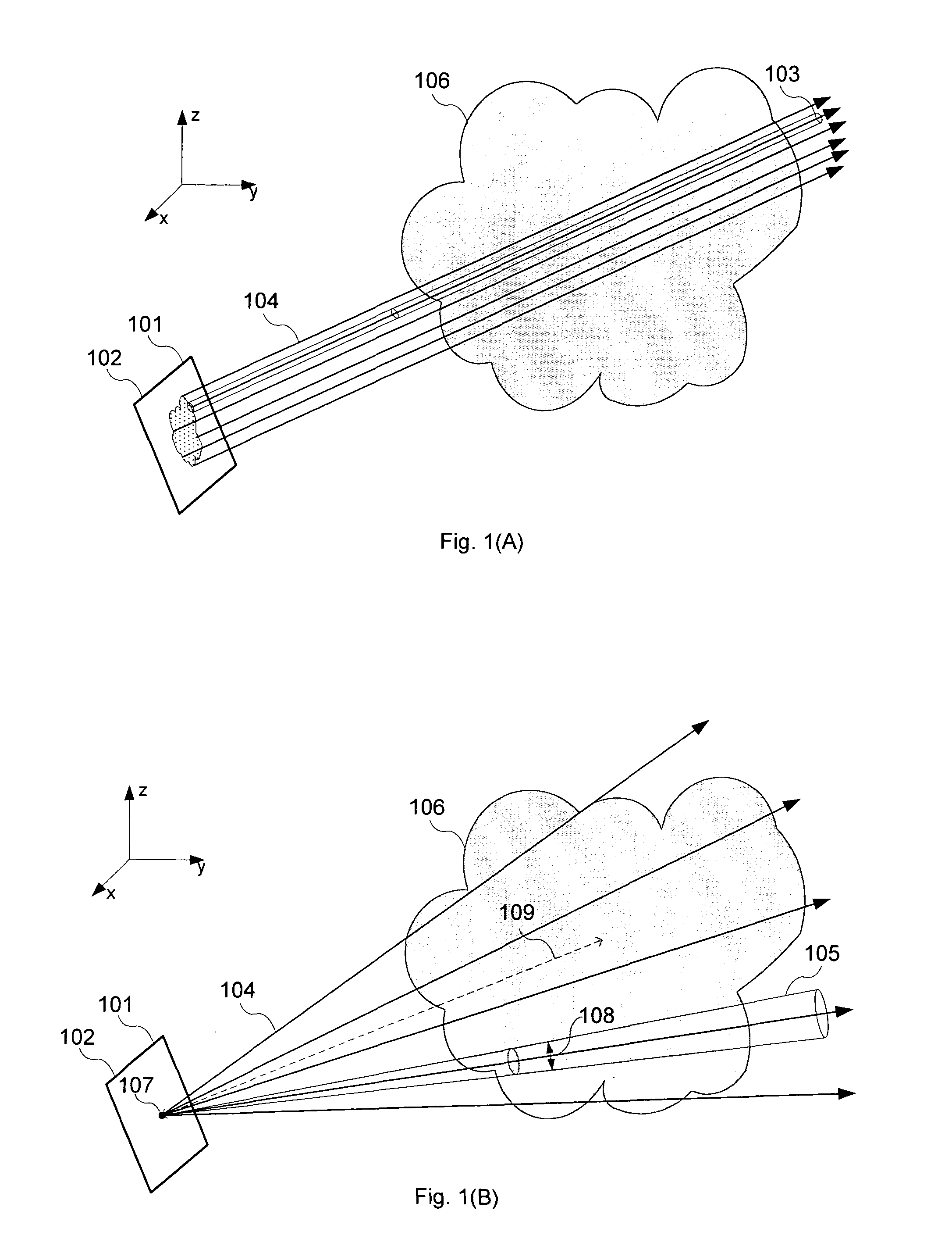
[0051] FIGS. 1(A) and 1(B) schematically illustrate the basic principle of direct volume rendering using the two embodiments of the present invention. In a 3-D domain represented by the Cartesian coordinates (x, y, z), there is an image volume 106 representing one or more 3-D objects. Direct volume rendering generates a 2-D image by casting a plurality of rays 104 into the image volume 106 and simulating the interactions between the rays and the image volume so as to visualize the 3-D characteristics of the 3-D objects. Note that the shape of a ray in the context of the present invention is not a 1-D line, but a 3-D tube or cone depending on different ray configurations discussed below.

[0052] In the embodiment shown in FIG. 1(A), the plurality of rays 104 are launched from different locations on a radiation plane 102, each ray traveling in parallel to another one towards the image volume 106. The shape of a ray is a tube 103 that has a cross-section of constant size, also referred ...


PUM


Abstract

An adaptive image volume rendering system first fragments a 3-D dataset into multiple sub-volumes and constructs an octree structure, wherein each sub-volume is associated with one node on the octree. The system then establishes a 2-D image plane and selectively launches a plurality of rays towards the 3-D dataset, each ray adaptively interacting with a subset of the sub-volumes. The ray energy reflected by each sub-volume is estimated using a modified Phong illumination model, constituting a pixel value at the ray origin on the 2-D image plane. Finally, the system interpolates pixel values at a plurality of selected locations and generates a 2-D image of the 3-D dataset.

Description

FIELD OF THE INVENTION [0001] The present invention relates generally to the field of volume data rendering, and more particularly, to a method and system for rendering a volume dataset using adaptive data representation, ray casting, and data interpolation techniques. BACKGROUND OF THE INVENTION [0002] Visualization of the internal structure of 3-D objects on a 2-D image is an important topic within the field of computer graphics and has been applied to many industries, including medicine, geoscience, manufacturing, and drug discovery. [0003] For example, a CT scanner can produce hundreds or even thousands of parallel 2-D image slices of a patient's body including different organs, e.g., a heart, each slice including a 2-D array of data values and each data value representing a scalar attribute of the body at a particular location, e.g., density. All the slices are stacked together to form an image volume or a volumetric dataset of the patient's body with the heart embedded therein...

Claims


Application Information

Patent Timeline
IPC IPC(8): G06T17/00G09G5/00
CPCG06T15/06G06T17/005G06T15/83G06T15/08
Inventor BUYANOVSKIY, GEORGIY
Owner FOVIA
Why Eureka
Try Eureka