
Video compression system

a video compression and video technology, applied in the field of computer data processing, can solve the problems of imposing different amounts of delay, serious problems, and sending too much data for the communication channel with resolution loss, and achieve the effect of reducing delay and maximizing compression of captured video

Active Publication Date: 2005-03-31
VERTIV IT SYST INC
View PDF37 Cites 88 Cited by
  • Summary
  • Abstract
  • Description
  • Claims
  • Application Information

AI Technical Summary

Benefits of technology

[0013] The present invention is a new video compression system that is optimized to take advantage of redundancies typically occurring on computer screens and also is optimized to take advantage of types of video loss acceptable to real time interactive computer users. In one embodiment of the present invention, captured frames of computer video are “encoded” into combinations of five different, uniquely chosen “commands”, which are selected and sequenced based on their ability to most efficiently compress the captured video. These commands are sent over the network to the “client” where they continuously instruct (or command) the “decoder” on how to decompress or decode the commands and recreate the captured video frames on the remote video display. In a unique way, this embodiment can compress and decompress computer video without resolution loss or color depth loss, but with frame rate loss that is dynamically adjusted depending on available network bandwidth. It also imposes minimal delay during encoding and decoding.
[0014] The five commands are; (1) copy old pixels from an earlier frame (sometimes called “no change from an earlier frame,”“no change” or simply “NC”), (2) copy pixel from the left, (3) copy pixels from above, (4) make a series of pixels using a 2-color set, and (5) make one or more pixels using a specified color. Each command provides unique efficiencies when employed in a hierarchical structure. Also, the commands are included in comprised of packets that are a fixed length of 8 bits or more, such that they can be easily sent, received and decoded with either software or hardware. The present invention is not limited to any command or packet length, but preferred embodiments would use lengths that were a multiple of 8-bits (such as 16, 32 or 64) such that they would be compatible with popular and commonly available components and processors.
[0015] In broader embodiments of the present invention, one, two, three, or four of the types of commands described above are used, alone or in any combination thereof. For example, the inventor believes that the use of the command to make a series of pixels from a 2-color set alone is unique in compressing video that includes a significant amount of alphanumeric text (such as viewing this document with a word processing program). Further advantages and efficiencies are gained when others of the commands are added thereto in various combinations. In other embodiments, one, two, three, four, or all five of the commands are used in conjunction with any kind of prior art compression system to enhance the video compression of the known system. For example, MPEG, JPEG, and others (and all variants thereof (e.g., MPEG2, etc.)) can be used with one or more of the five commands described herein to enhance the video compression of the prior art compression techniques.
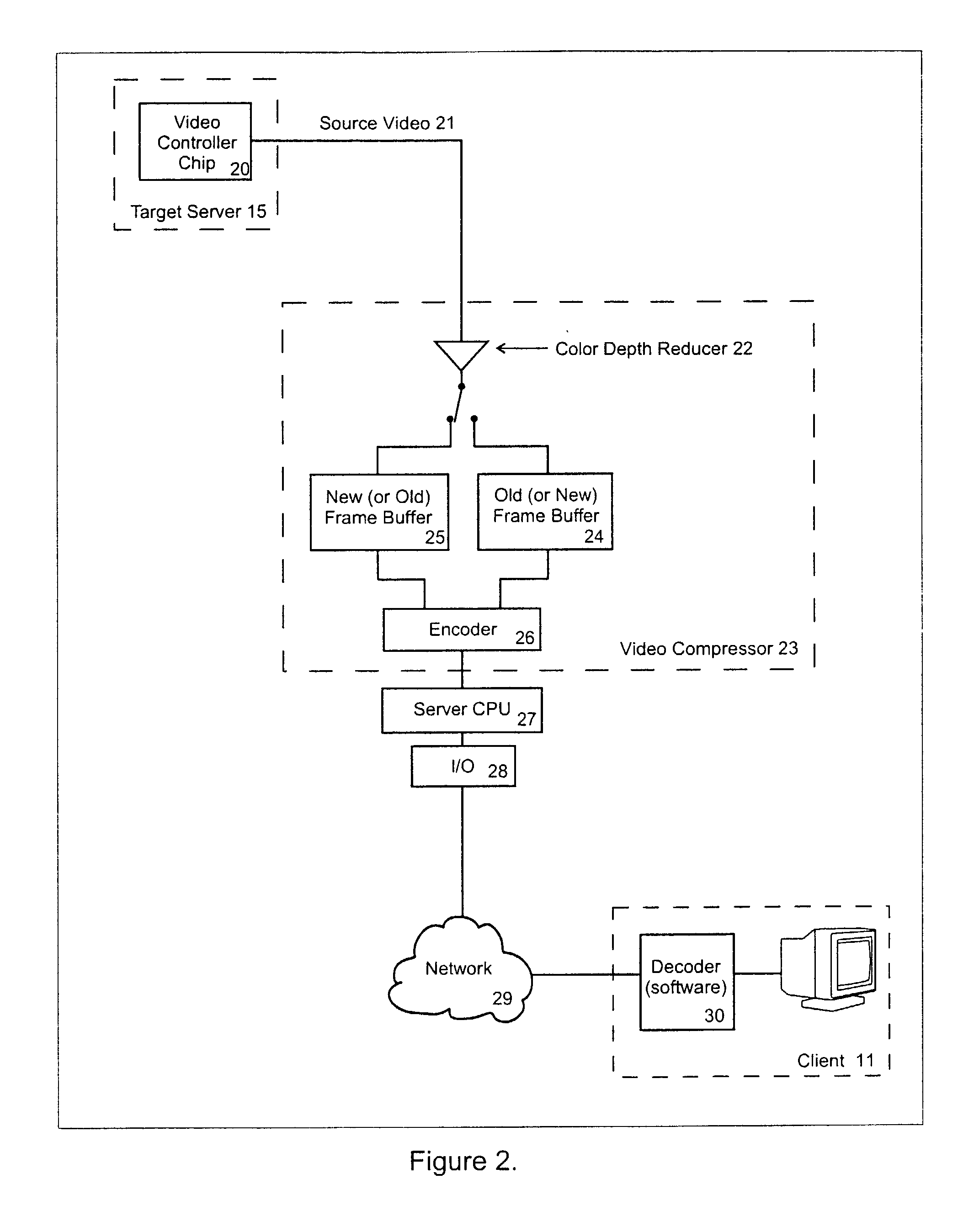
[0018] The video compression commands are sent over a network to the remote console where they are decompressed and displayed to the user. The remote console can be a conventional PC (personal computer), which decodes the commands using PC software or it could be a small “thin client” device built with a low performance microprocessor. In one embodiment, the commands are all designed to consist of one or more 8-bit packets so that they can be easily decompressed with software running on a low performance microprocessor. Alternatively, a hardware device (such as an FPGA or ASIC) can completely decode the commands at the remote console. In such a case, the remote console would not require a computing device for command decoding or a video controller chip for displaying the user's video. Such a low-cost hardware (or combined hardware / software) remote console is referred to below as a “microclient.”

Problems solved by technology

For example, with MPEG, fast action scenes that would generate too much data for the communication channel are sent with resolution loss because movie viewers accept resolution loss better than they accept frame rate loss or color depth loss.
Video delay is not a problem in some applications but it is a serious problem in other applications.
Different compression systems impose different amounts of delay as they compress the video.
Although time delay is not a problem with one-way user activities such as watching movies, it is a serious problem for real time “interactive” users, such as users with a mouse, controlling a cursor that is a part of the compressed video image.
Delays in sending the video back to the remote console user are annoying because they create a temporal lag between the entry of the keyboard or mouse information by the user and the video response perceived by the user on their screen.
This problem of remote console applications (described above) is not applicable to some types of typical web browser applications.
Compression systems such as JPEG or MPEG, that impose resolution loss may be satisfactory for many other applications, but they are not satisfactory for reading small font alphanumeric text and images with high contrast sharp edges.

Method used


Image

  • Video compression system
  • Video compression system
  • Video compression system

Examples


Embodiment Construction

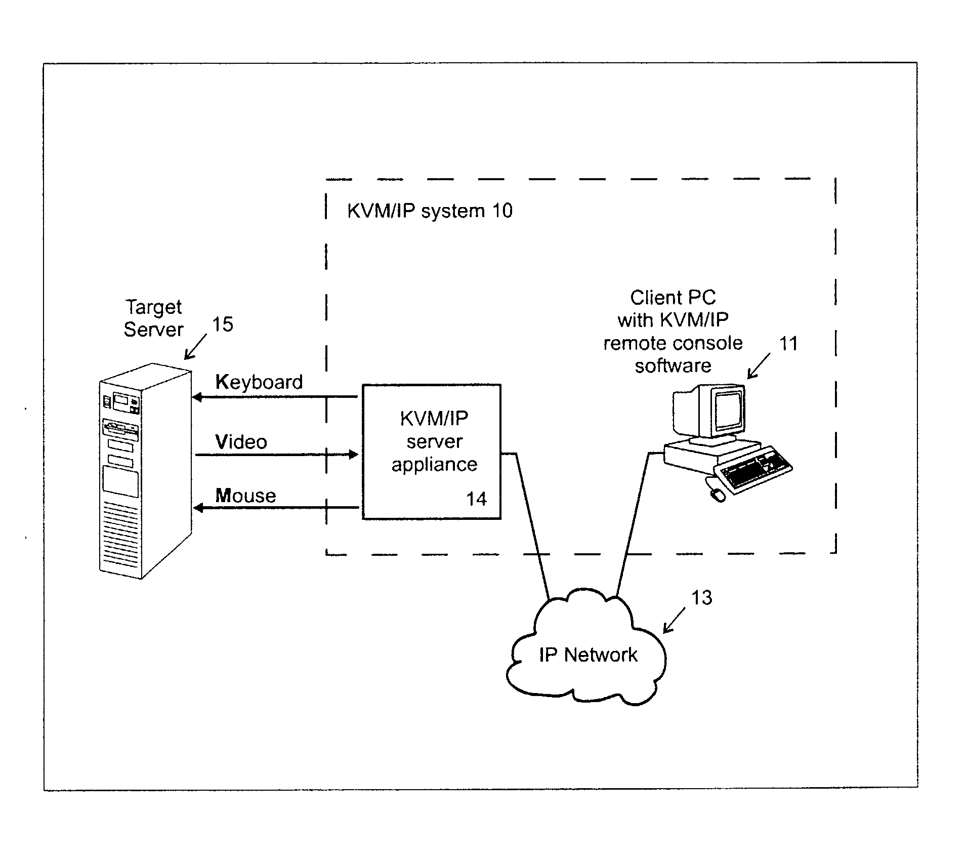
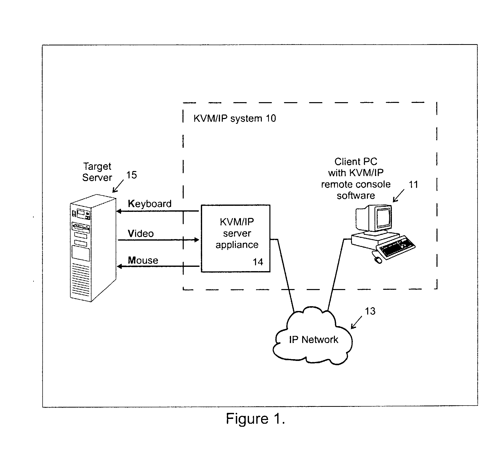
[0034] The present invention can be implemented with any hardware or software that aims to send computer video over a communication channel, including over an intervening network. One such example embodiment is shown in FIG. 1, which is described by way of example rather than limitation. Indeed other embodiments will be understood once the artisan reviews the invention, as embodied in the appended Figures and described herein.

[0035] In FIG. 1, the KVM / IP system 10 includes a remote console client 11 and a server appliance 14. In the embodiment shown, the remote console 11 is implemented with PC software in a network-ready PC (which includes a keyboard, video display and mouse). The client 11 communicates via an Internet Protocol network 13, to a target server 15 via the KVM / IP appliance 14. The appliance 14 and the client 11 include standard network I / O hardware and software to permit them to communicate via any form of Internet protocol connectivity, such as a dial-in, DSL, WAN, L...


PUM


Abstract

A video compression system is disclosed that is optimized to take advantage of the types of redundancies typically occurring on computer screens and the types of video loss acceptable to real time interactive computer users. It automatically adapts to a wide variety of changing network bandwidth conditions and can accommodate any video resolution and an unlimited number of colors. The disclosed video compression encoder can be implemented with either hardware or software and it compresses the source video into a series of data packets that are a fixed length of 8 bits or more. Sequences of one or more of these packets create unique encoding “commands” that can be sent over any network and easily decoded (decompressed) with either software or hardware. The commands include 3 dimensional copying (horizontal, vertical and time) and unique efficiencies for screen segments that are comprised of only two colors (such as text). Embodiments are also disclosed that improve the video compression depending on the popularity of pixel colors.

Description

FIELD OF THE INVENTION [0001] This invention relates to computer data processing, and more particularly to computer video compression. BACKGROUND OF THE INVENTION [0002] Existing video compression systems can compress a stream of video data so it takes less bandwidth to send over a communication channel. Such systems take advantage of redundancies expected to occur in the video they are aiming to compress. For example, JPEG and MPEG take advantage of frequent similarities in the colors of adjacent pixels in photographic images. In addition, MPEG takes advantage of the fact that motion pictures often have many pixels that stay the same color during many frames of video or only shift their positions on the screen as the camera moves. [0003] Video can be further compressed depending on how much degradation in video quality (or “video loss”) is acceptable to the person (or “user”) viewing the video, but the acceptability of different types of video loss is highly dependent on the user's...

Claims


Application Information

Patent Timeline
Patent Type & Authority Applications(United States)
IPC IPC(8): G06T9/00H04N7/26H04N7/36H04N19/593
CPCG09G2370/24H04N19/00387H04N19/105H04N19/593H04N19/507H04N19/20H04N19/426H04N19/93H04N19/182
Inventor DAMBRACKAS, WILLIAM A.
Owner VERTIV IT SYST INC
Learn More