
Power control with signal quality estimation for smart antenna communications systems

a technology of power control and signal quality estimation, applied in power management, transmission monitoring, electrical equipment, etc., can solve problems affecting communication quality

Inactive Publication Date: 2011-11-22
INTEL CORP
View PDF191 Cites 210 Cited by
  • Summary
  • Abstract
  • Description
  • Claims
  • Application Information

AI Technical Summary

Problems solved by technology

The resulting new weight vector is used and may affect the quality of communication.

Method used


Image

  • Power control with signal quality estimation for smart antenna communications systems
  • Power control with signal quality estimation for smart antenna communications systems
  • Power control with signal quality estimation for smart antenna communications systems

Examples


Embodiment Construction

System Architecture

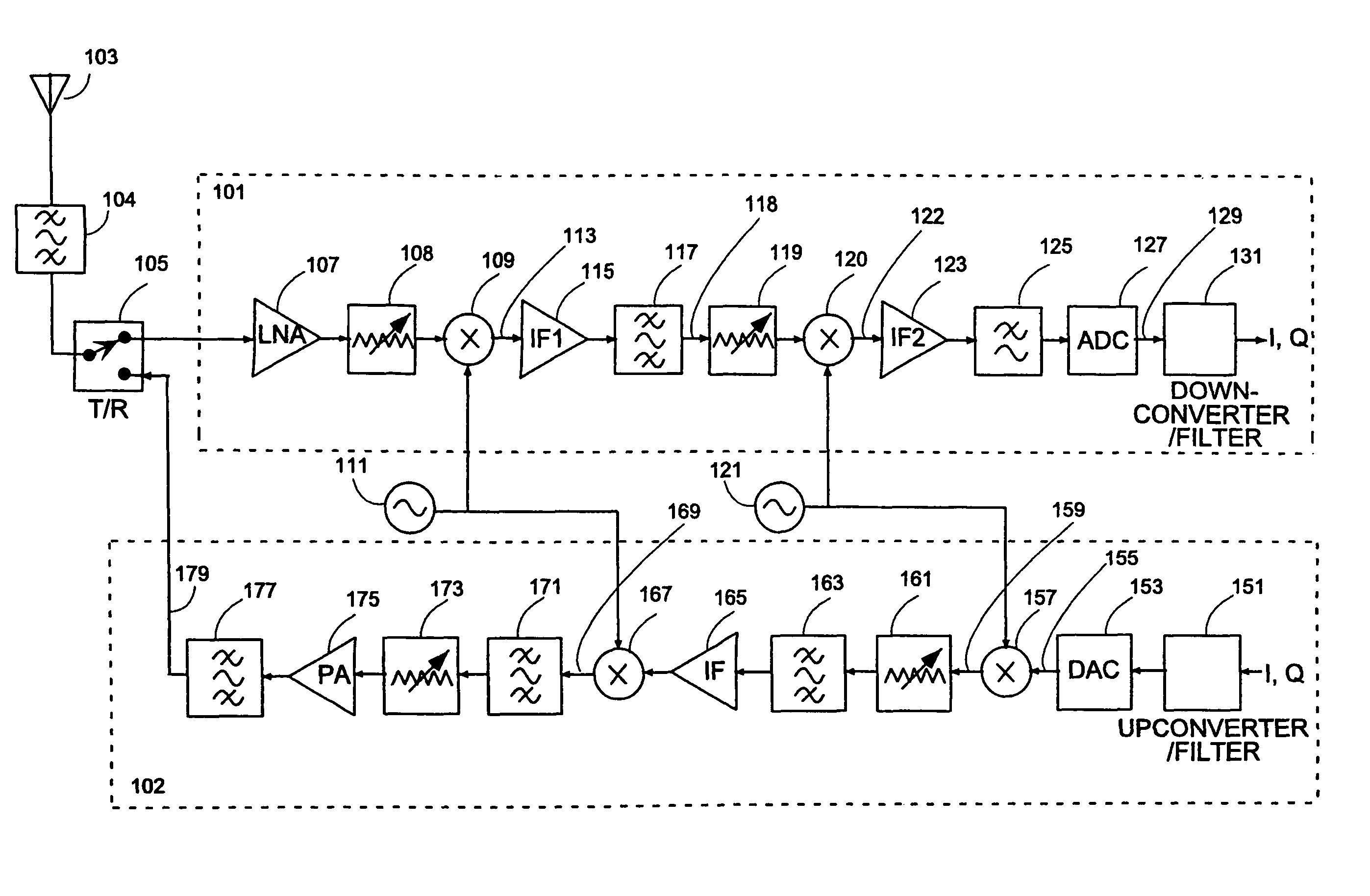
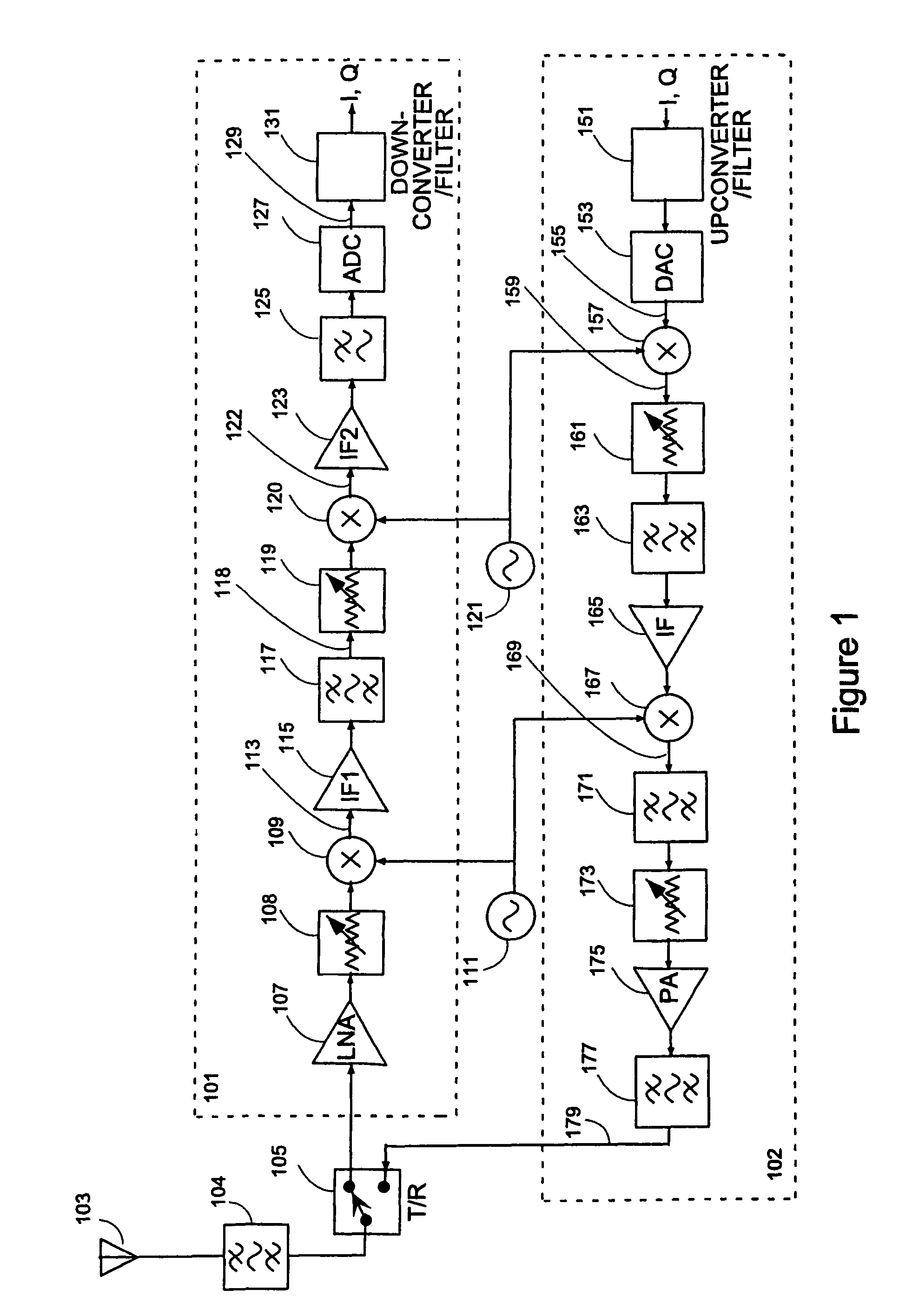
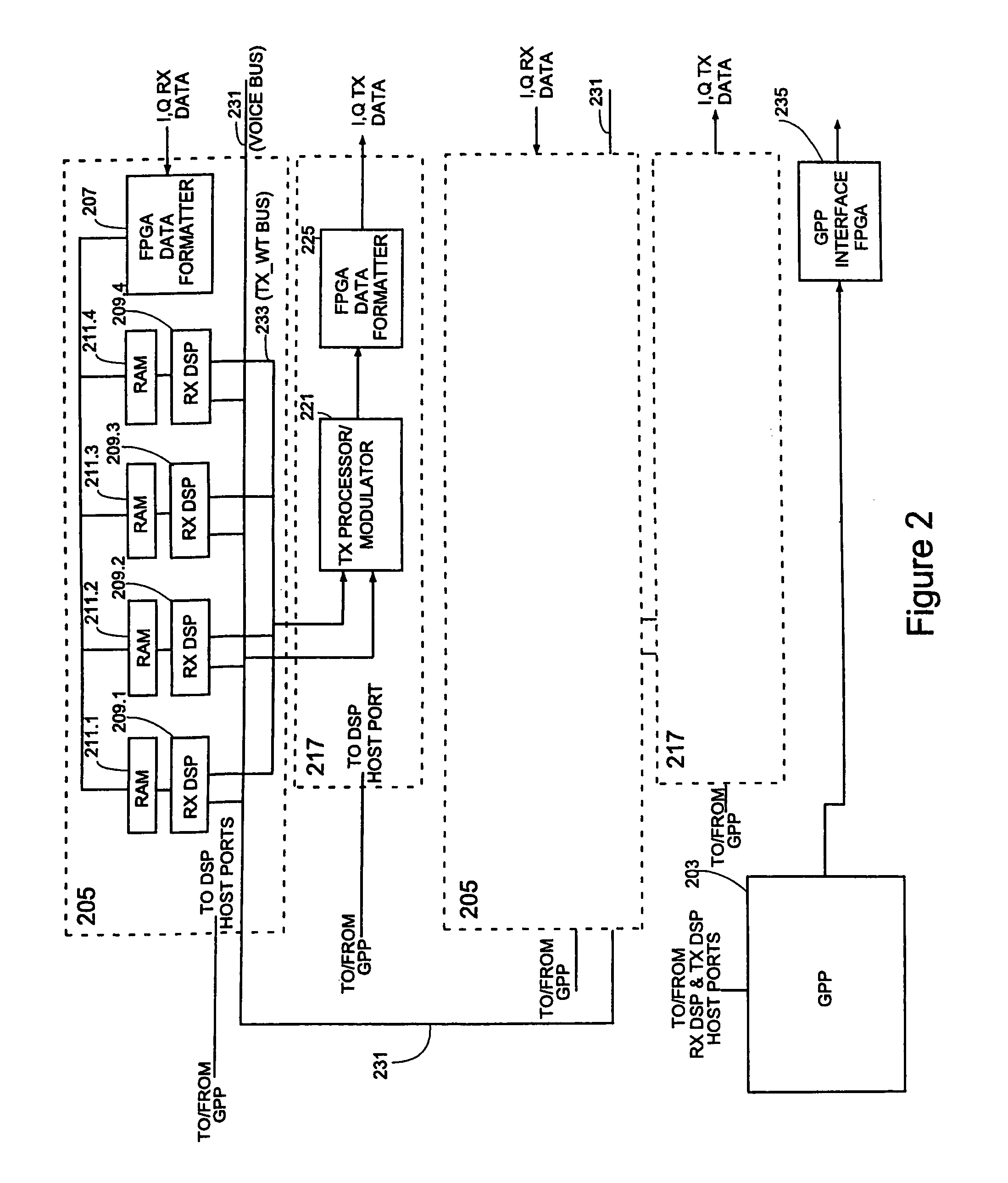
[0062]The methods of the invention may be implemented on any communication system which includes one or more communication stations and one or more remote receivers (for communication on the downlink) and transmitters (for communication on the uplink). The only requirement for the quality estimation aspects of the invention is that the modulation used includes some form of angle (e.g., phase) demodulation, and the only requirement for the downlink SDMA power control is the ability to determine downlink transmit weights, for example from received uplink signals. The methods of the invention preferably are implemented on a communication station which is a base station and on its subscriber units, which are part of a communication system in which a base station uses SDMA to communicate with its subscriber units. In the preferred embodiment, the communication system is meant for use in a wireless local loop (WLL) cellular system. While the subscriber units in the illu...


PUM


Abstract

A method for power control with signal quality estimation for smart antenna communications system is described. The method, for example, starts with a transmit power assignment. Receive weight vector determination is carried out with this assigned transmit power, and the new weights used. An estimate of the resulting received signal quality is obtained and used for another power adjustment.

Description

CROSS-REFERENCE TO RELATED APPLICATION[0001]This application is a continuation of U.S. patent application No. 10 / 231,782, filed Aug. 28, 2002, entitled “Power Control with Signal Quality Estimation for Smart Antenna Communications Systems”, which, in turn, is a Continuation-In-Part of U.S. patent application Ser. No. 09 / 020,049, filed on Feb. 6, 1998, entitled “Power Control with Signal Quality Estimation for Smart Antenna Communications Systems”, now U.S. Pat. No. 6,463,295, issued on Oct. 8, 2002, which, in turn, is a Continuation-In-Part of U.S. patent application Ser. No. 08 / 729,387, Filed on Oct. 11, 1996, entitled “Adaptive Method For Channel Assignment In a Cellular Communication System”, now U.S. Pat. No. 6,047,189, issued on Apr. 4, 2000, the priority of each of which are hereby claimed.FIELD OF INVENTION[0002]This invention relates to the field of wireless communication systems and more particularly to controlling radiated RF power level during establishment of a call and ...

Claims


Application Information

Patent Timeline
Patent Type & Authority Patents(United States)
IPC IPC(8): H04B7/00
CPCH04W52/42H04B7/0848
Inventor YUN, LOUIS C.
Owner INTEL CORP
Learn More