On-site power plant control including adaptive response to transient load requirements

a technology of adaptive response and power plant, applied in the direction of machine/engine, process and machine control, instruments, etc., can solve the problems of increasing utility demand charges, unable to heat or cool the facility, and controlling the operation of such on-site power plants, so as to avoid tripping the relay

Active Publication Date: 2011-11-22
RTX CORP
View PDF21 Cites 8 Cited by
  • Summary
  • Abstract
  • Description
  • Claims
  • Application Information

AI Technical Summary

Benefits of technology

[0011]By maintaining at least one of the prime movers in operation, the disclosed example avoids shutting down the entire on-site power plant responsive to a down transient in the power requirements at a load whenever such continued operation is possible while avoiding tripping the relay. This example provides the benefit of continuing to realize the advantage of having an on-site power plant while also avoiding exporting power to a grid in a manner that would otherwise result in shutdown of the on-site power plant by tripping a reverse power protective relay.
[0012]One example includes determining a capacity for fueling the on-site power plant based upon an operating condition of a fuel gas booster, for example. The determined capacity is then used to determine how to control the prime movers such as selecting an appropriate number of prime movers for operation. By controlling which of the prime movers operates responsive to available fuel capacity, the disclosed example avoids shutdowns of the on-site power plant that are otherwise associated with unmatched fuel consumption and fuel supply capacity.

Problems solved by technology

There are various challenges in controlling the operation of such on-site power plants.
That solution has drawbacks including potentially leaving the facility without heating or cooling for some period of time, which requires incurring increased utility demand charges.
Additionally, the locally generated power from the on-site power plant may not be provided for an extended period of time, which defeats the purpose of having the on-site power plant.
Another issue with existing arrangements is that the exhaust gas stream provided to the cogeneration unit does not always correspond to the demand for heating or cooling within the facility.
In many circumstances, there are efficiency losses because excess exhaust gas from the prime movers is vented to atmosphere, supplementary heaters or chillers are required to maintain a desired temperature within the facility, or both.
There has been no arrangement, however, that utilizes such information in controlling the prime movers of an on-site power plant.
Another issue associated with known arrangements is that the natural gas fuel provided to the prime movers typically must be processed (e.g., through a booster).
There are situations where one or more fuel boosters may malfunction or be temporarily taken out of service for repair or routine maintenance, for example.
Under such circumstances, known arrangements tend to shutdown the entire on-site power plant because the available capacity for fueling is not adequate for operating the prime movers that are running under such circumstances.
Additionally, during start up of prime movers, high inlet gas pressures require higher fuel consumption rates compared to normal operation.
This adds cost to a system, which is undesirable.

Method used


Image

  • On-site power plant control including adaptive response to transient load requirements
  • On-site power plant control including adaptive response to transient load requirements
  • On-site power plant control including adaptive response to transient load requirements

Examples


Embodiment Construction

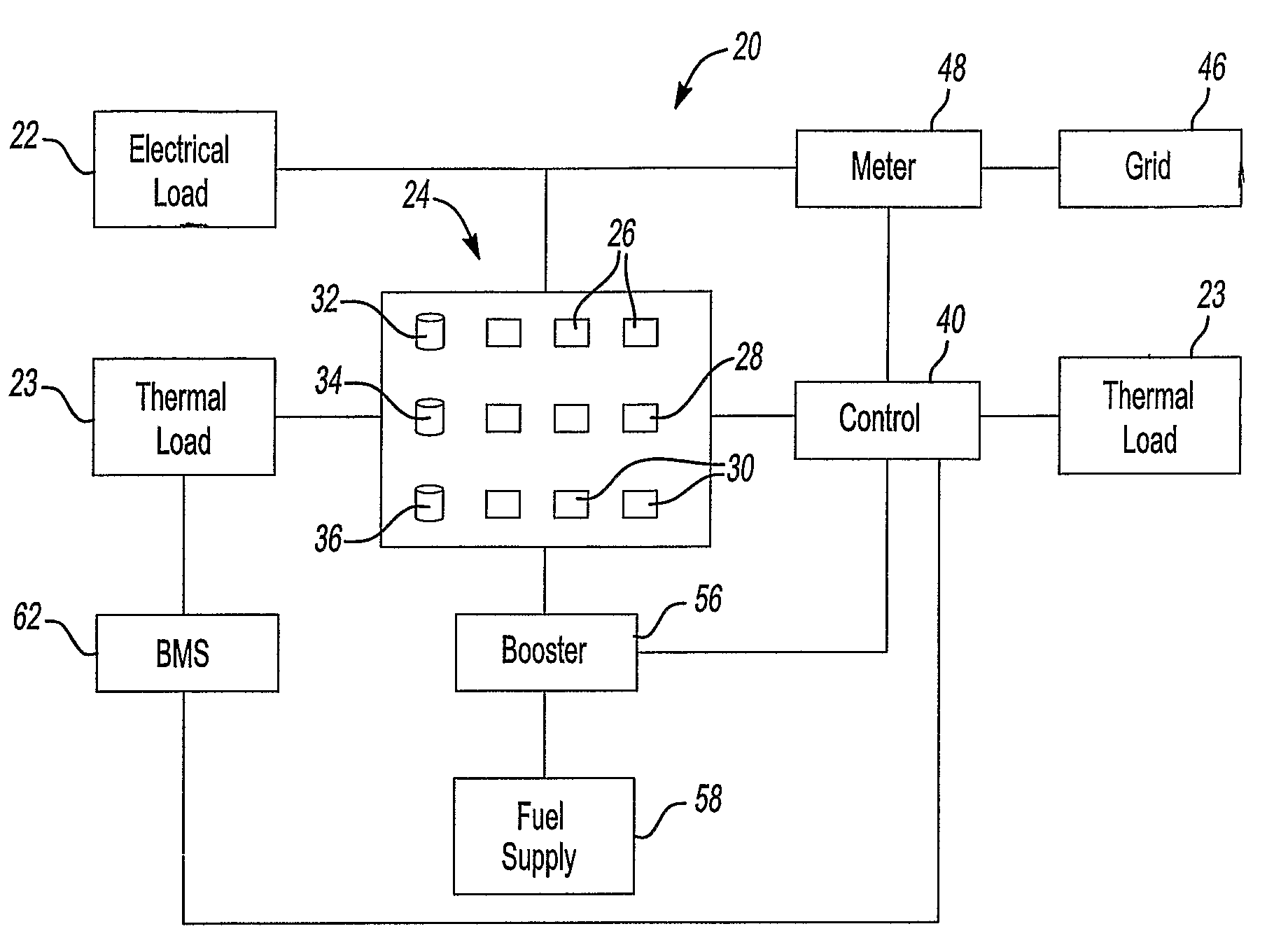
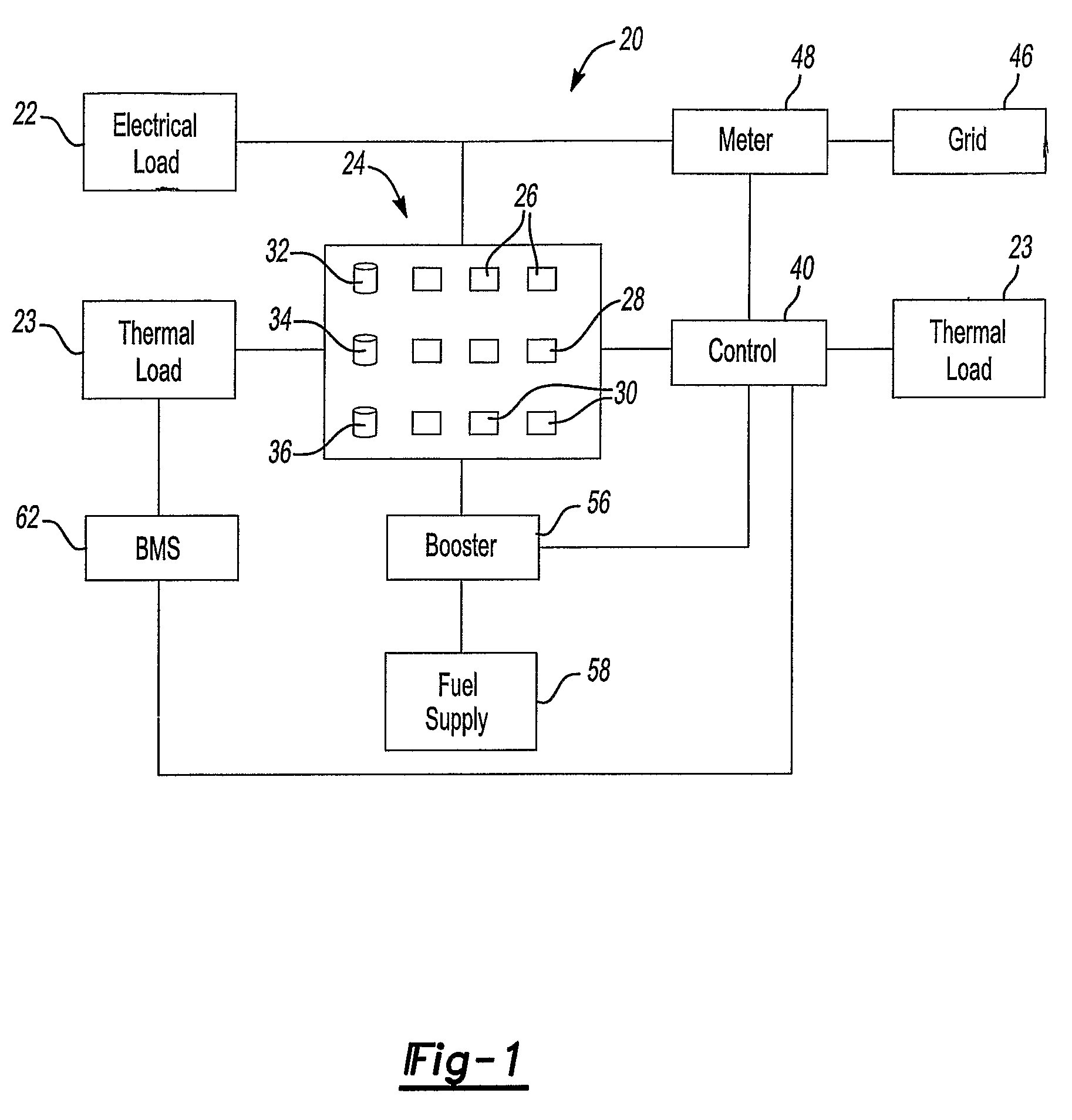
[0018]FIG. 1 schematically shows a system 20 for providing power to a facility such as a building. The facility is schematically shown as an electrical load 22 and a thermal load 23 in the illustration. An on-site power plant 24 includes components arranged in a known manner for generating power for use by the electrical load 22 and to provide temperature control for the thermal load 23. In the illustrated example, the on-site power plant 24 includes a plurality of prime movers for generating power. In one example, the prime movers comprise microturbines.

[0019]In the illustrated example, the prime movers are grouped such that there are a first plurality of prime movers 26, a second plurality of prime movers 28 and a third plurality of prime movers 30. Each plurality of prime movers is associated with a cogeneration unit in a known manner. The cogeneration unit 32 is associated with the plurality of prime movers 26. Another cogeneration unit 34 is associated with the prime movers 28 ...


PUM


Abstract

An on-site power plant (24) has a controller (40) that selectively controls operation of prime movers (26, 28, 30). In one example, the controller (40) changes the number of operating prime movers responsive to a transient in a load (22) requirement while continuing to operate at least one of the prime movers. One example includes prioritizing the prime movers (26, 28, 30) for operation based upon the needs of a cogeneration unit (32, 34, 36) associated with the prime movers for providing a temperature control function within a facility. Another example includes controlling operation of the prime movers based upon a capacity for fueling the prime movers.

Description

FIELD OF THE INVENTION[0001]This invention generally relates to on-site power plants. More particularly, this invention relates to controlling operation of the components of an on-site power plant.DESCRIPTION OF THE RELATED ART[0002]On-site power plants are known. Typical arrangements include a plurality of prime movers for generating power. Microturbines serve as the prime movers in some examples.[0003]Most on-site power plants provide electrical power to a facility such as a building. Some on-site power plants provide thermal energy, electrical energy and include temperature control functions to provide heating or cooling to a facility. Such arrangements typically include a cogeneration unit that operates based upon exhaust from a microturbine. Depending on the need for heating or cooling within the facility, the cogeneration unit operates in a corresponding fashion, utilizing exhaust from the prime movers according to the arrangement of a particular system.[0004]In some situation...

Claims


Application Information

Patent Timeline
Patent Type & Authority Patents(United States)
IPC IPC(8): G06F19/00
CPCF01K13/02Y02E20/14Y02P80/15
Inventor KAMAT, MITHUN R.ATKINSON, SARA E.MORROW, AARON W.LAVIGNE, DAVID P.ZHU, GUANG-YAN
Owner RTX CORP
Why Eureka
Try Eureka