Start-up circuit, core circuit, consumable chip, consumables, start method of bandgap reference circuit and working method of core circuit

A reference circuit and start-up circuit technology, applied in the direction of adjusting electrical variables, control/regulation systems, instruments, etc., can solve problems such as low drain potential, failure of triode conduction, and abnormal start-up of the circuit

Pending Publication Date: 2019-02-15
HANGZHOU CHIPJET TECH
View PDF0 Cites 8 Cited by
  • Summary
  • Abstract
  • Description
  • Claims
  • Application Information

AI Technical Summary

Problems solved by technology

[0007] (3) The input terminal of the operational amplifier OPA is at a certain potential, but it cannot make the transistor Q 0 , Q 1 conduction, so the circuit is in an unknown state
[0009] 1) Due to the resistor R 3 and R 4 the presence of MP 1 , MP 3 The drain potential is very low, not enough to turn on the transistor Q 0 , Q 1 when R 3 and R 4 Provide a current path for the circuit so that the circuit is at the third degeneracy point, causing the circuit to fail to start normally
[0010] 2) After the abnormal drop of the power supply voltage changes and returns to stability, the circuit may also be at the third degeneracy point

Method used


Image

  • Start-up circuit, core circuit, consumable chip, consumables, start method of bandgap reference circuit and working method of core circuit
  • Start-up circuit, core circuit, consumable chip, consumables, start method of bandgap reference circuit and working method of core circuit
  • Start-up circuit, core circuit, consumable chip, consumables, start method of bandgap reference circuit and working method of core circuit

Examples


Embodiment 1

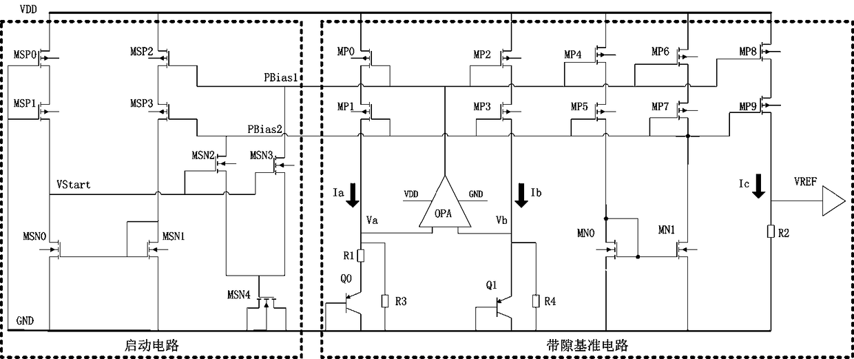
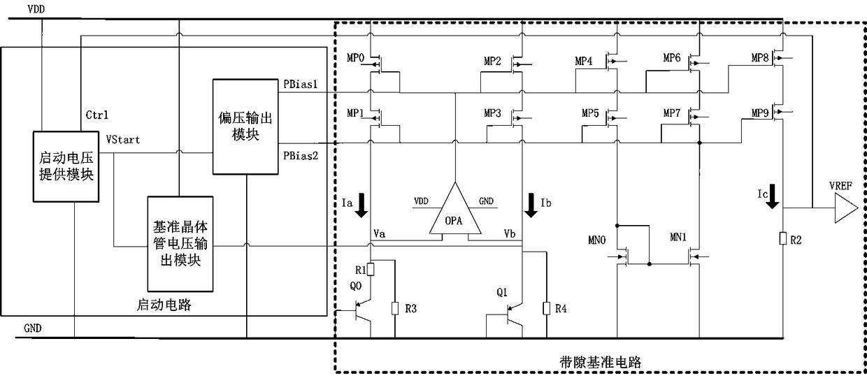
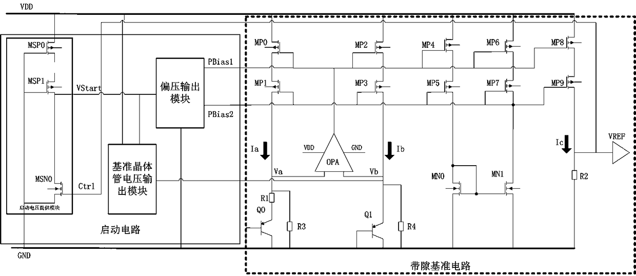
[0050] A core circuit includes: a bandgap reference circuit and a starting circuit for starting the bandgap reference circuit. Such as figure 2 As shown, the core circuit includes a start-up circuit composed of a start-up voltage supply module, a bias voltage output module, a reference transistor voltage output module, and a bandgap reference circuit composed of other devices.

[0051] The startup circuit consists of:

[0052] The first voltage output terminal PBias1, and the first bias voltage input terminal (field effect transistor MP) of the bandgap reference circuit 8 / MP 6 / MP 4 / MP 2 / MP 0 grid) electrical connection;

[0053] The second voltage output terminal PBias2, and the second bias voltage input terminal of the bandgap reference circuit (field effect transistor MP 9 / MP 7 / MP 5 / MP 3 / MP 1 gate or MP 7 drain) electrical connection;

[0054] The third voltage output terminal Vb, and the reference transistor Q of the bandgap reference circuit 1 The em...

Embodiment 2

[0081] A chip for consumables, including the core circuit described in Embodiment 1.

Embodiment 3

[0083] A consumable includes the consumable chip described in the second embodiment.


PUM


Abstract

The invention relates to the technical field of start-up technology of bandgap reference circuit, in particular to a start-up circuit, a core circuit, a consumable chip, consumables, the start methodof the bandgap reference circuit and the working method of the core circuit. When the startup circuit is powered on, the first bias input and the second bias input of the bandgap reference circuit arebiased to break the zero current state of the bandgap reference circuit. The control end of the startup circuit is connected to the output end of the bandgap reference circuit, so that the startup circuit can be turned off only when the output voltage of the bandgap reference circuit reaches the expected voltage value. When the start-up circuit is powered on, the third voltage output terminal directly provides the working current for the reference transistor, which makes the reference transistor out of the zero current state and enter the normal working state.

Description

technical field [0001] The invention relates to the technical field of starting circuits for bandgap reference circuits, and in particular to starting circuits, core circuits, consumable chips, consumables, starting methods for bandgap reference circuits, and working methods for core circuits. Background technique [0002] The bandgap reference circuit uses the negative temperature coefficient of the PN junction voltage and the positive temperature coefficient of the voltage difference between the two PN junctions under different current densities to compensate each other, so as to obtain an output voltage with low temperature drift. Theory proves that this output voltage value is approximately equal to the bandgap voltage of silicon, so this circuit is called a bandgap reference circuit. A bandgap reference circuit usually forms a power supply together with a start-up circuit to provide a stable voltage output. When the power supply is powered up, in the absence of a start...

Claims


Application Information

Patent Timeline
Patent Type & Authority Applications(China)
IPC IPC(8): G05F1/56
CPCG05F1/561
Inventor 路和超胡容铭
Owner HANGZHOU CHIPJET TECH
Why Eureka
Try Eureka