Portable blind and concealment system

a concealment system and portable technology, applied in the field of concealment systems, can solve problems such as difficulty in seeing blindness

Active Publication Date: 2011-11-29
AMERICAN PRIDE OUTDOORS LLC
View PDF24 Cites 14 Cited by
  • Summary
  • Abstract
  • Description
  • Claims
  • Application Information

AI Technical Summary

Benefits of technology

[0008]A concealment system is provided to effectively hide or conceal human movement, the human form and / or other structures, such as machinery, equipment or vehicles.
[0009]In one embodiment, the concealment system is incorporated into a hunting or wildlife observation blind, referred to herein as a “blind.” The blind can be portable and collapsible, and generally of the hub-style variety. The blind can include one or more walls and an optional roof. The blind can be configurable in a collapsed mode in which the blind is usually transported, and a erected mode in which the blind is fully erected and ready for concealment. The blind can also include one or more simulated arborescent structures which generally include a limb and a leafy part joined with the limb. The limb and / or leafy part can extend beyond the physical borders such as corners and edges of the blind to effectively break up its geometric shape, thereby blending the blind in with natural surroundings.
[0011]In yet another embodiment the positioning members can be configured to align the limbs of the simulated arborescent structures so that they are generally parallel to corners or edges of the blind, and / or to support members of a frame. Accordingly, the positioning members can generally align multiple limbs with one another, as well as the support members of the frame, to aid in the collapsing of the frame and / or blind to a collapsed state.
[0013]In another embodiment, the limb of the simulated arborescent structures can include a wire or rod embedded in a plastic or composite material. The limbs can be formable in a number of desired configurations. The leafy parts can include from a different wire or rod, formed, for example from a harder material or metal, such as spring steel. The leafy parts also include can a fabric that is joined with the wire or rod. When used with the blind, the limbs and leafy parts are adapted to resume a full and extended state, so that when the blind is erected, these elements extend beyond the boundaries and peripheries of the geometric shape of the blind. Accordingly, the blind readily attains a “brushed in” appearance without significant work on the part of the user.
[0014]In yet a further embodiment, the blind can include a concealment pod, or “star”, joined with the blind at pre-selected locations. The concealment pod can include a base having multiple mounting members to which the simulated arborescent structures can be joined. A joining element can be joined with a base opposite the simulated arborescent structures. The joining element can be pivotally joined with the base, and thus rotatable to reorient the simulated arborescent structures, relative to a structure such as the blind, to which the pod is joined. Accordingly, the simulated arborescent structure can provide a desired camouflaging effect to the structure and / or blind.
[0017]In yet another, further embodiment, the joining element can define a slot sized to accept a web or other structure so that the pod can be readily joined with the web or structure.

Problems solved by technology

When the blind is in the erected mode, one or more limbs extend beyond the geometric shape a sufficient distance to visually break up the geometric shape so that the blind is difficult to perceive.

Method used


Image

  • Portable blind and concealment system
  • Portable blind and concealment system
  • Portable blind and concealment system

Examples


Embodiment Construction

I. Overview

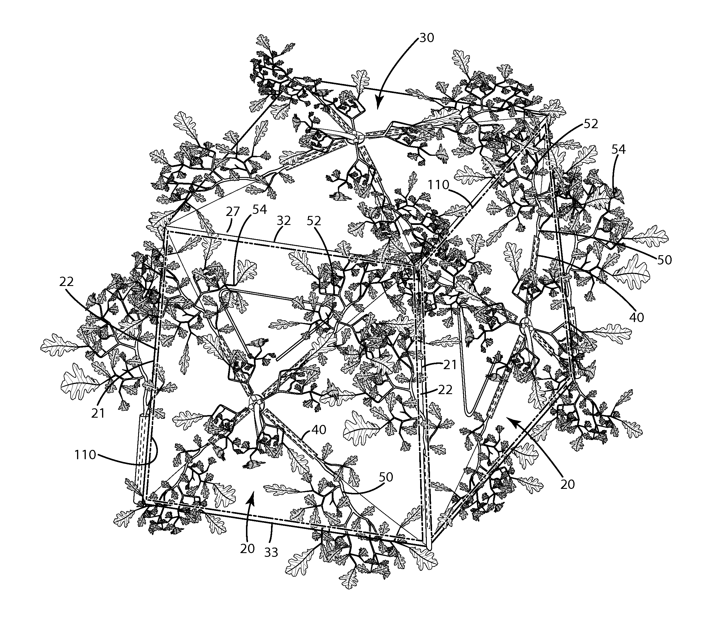
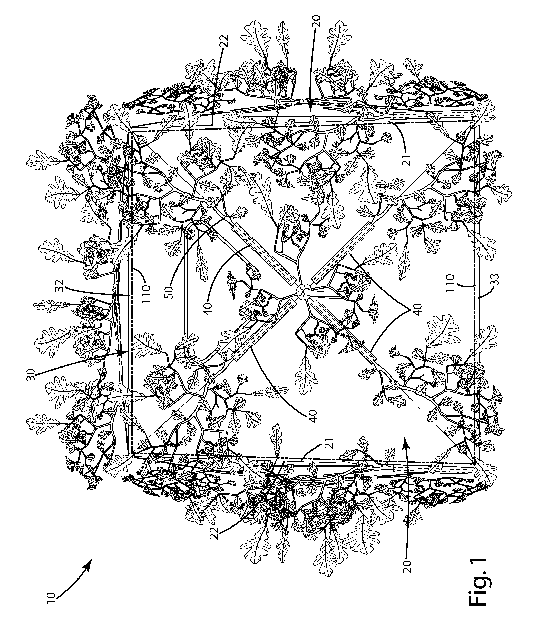
[0037]A concealment system of a current embodiment includes an enclosure in the form of a portable, collapsible blind, illustrated in FIGS. 1-2 and 4, and generally designated 10. The blind 10 can include multiple side walls 20 and a roof 30. The side walls 20 can include side edges 21, and can be joined with one another at side wall corners 22. The side walls 20 can be joined with the roof 30 at the roof corners 32, which also can correspond to the upper edges 37 of the walls. The side walls 20 can each also include lower edges 33. The side walls 20 and optionally the roof 30 can be formed from a frame 60 and a material 26 as described below. The frame 60 and material 26, and optionally the sidewalls 20 and / or roof 30, can form a geometric shape, such as a box, pyramid, dome or other geometric shape, when the blind 10 is erected. The side walls and roof can be covered or otherwise include a material 26, which can be a fabric. The material 26 is operable in a taut mode, w...


PUM


Abstract

A portable collapsible blind is provided including positioning members and simulated arborescent structures to break-up the hard geometric shape and lines of the blind. The positioning members can position the simulated arborescent structures to extend beyond at least one of a sidewall, side edge, upper edge, sidewall corner, roof edge, roof corner and roof a preselected distance. The simulated arborescent structure can include a limb and a leafy part suspended by the limb at a location distal from the geometric shape of the blind. A concealment pod also can be provided. The concealment pod can include a base with a plurality of outwardly projecting simulated arborescent structures. The base can include the fastener element that joins with a corresponding fastener element of a joining element. The base and joining element can be pivotally joined so that the simulated arborescent structures can be oriented in a variety of configurations.

Description

BACKGROUND OF THE INVENTION[0001]The present invention relates to a concealment system, and more particularly, to a portable concealment system for blinds and other structures.[0002]There are a variety of hunting and wildlife observation products that are adapted to conceal movement of a hunter or wildlife observer from game, such as deer, turkey and waterfowl. One such product is the ground blind.[0003]Ground blinds include a frame covered by panels constructed of a camouflage material that blends in the natural surroundings. The frame and material usually form an enclosure in which a hunter or wildlife observer conceals themselves. The camouflage material is usually opaque so that a hunter can move within the enclosure without alerting game to the hunter or observer's presence within the blind.[0004]Similarly, the military and police also use a variety of products to conceal the human form, equipment and / or machinery. For example, there are a variety of camouflage netting systems ...

Claims


Application Information

Patent Timeline
Patent Type & Authority Patents(United States)
IPC IPC(8): E04H15/48
CPCE04H15/001E04H15/48Y10S135/901
Inventor SCHLIPF, JARED SHANE
Owner AMERICAN PRIDE OUTDOORS LLC
Why Eureka
Try Eureka