Counterweight arrangement structure in elevator traction system

A technology for elevator traction and layout structure, which is applied to elevators in buildings, lifting equipment in mines, elevators, etc., and can solve the problem of destroying the overall appearance of fully transparent sightseeing elevators or home elevators, and unfavorable multi-directional free setting of car doors To achieve the effect of improving the overall look and feel, reducing and simplifying the layout structure, and symmetrically balancing the traction force

Pending Publication Date: 2019-04-23
SHAANXI SIUSAI ELECTROMECHANICAL TECH CO LTD
View PDF1 Cites 4 Cited by
  • Summary
  • Abstract
  • Description
  • Claims
  • Application Information

AI Technical Summary

Problems solved by technology

[0004] The purpose of the present invention is to solve the problem that the existing elevator counterweight layout structure in the hoistway is not conducive to the multi-directional free setting of the car door, and will destroy the overall look and feel of the fully transparent sightseeing elevator or home elevator. The counterweight layout structure in the elevator traction system facilitates the multi-directional free setting of the elevator car door, and at the same time can significantly improve the overall look and feel of the fully transparent sightseeing elevator and home elevator

Method used


Image

  • Counterweight arrangement structure in elevator traction system
  • Counterweight arrangement structure in elevator traction system
  • Counterweight arrangement structure in elevator traction system

Examples


Embodiment Construction

[0027] The present invention will be further described below in conjunction with the accompanying drawings and specific embodiments.

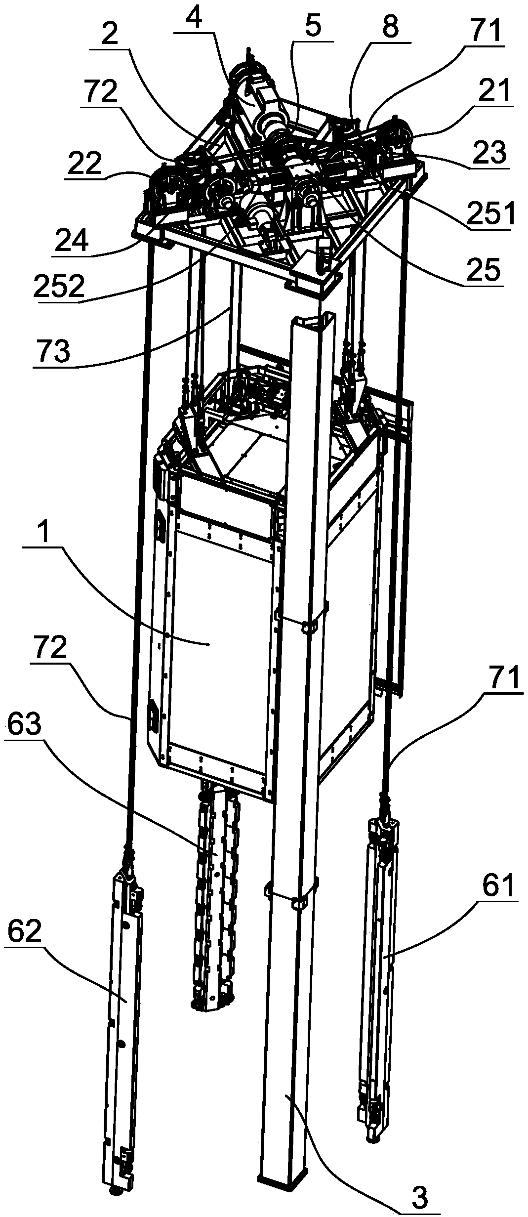
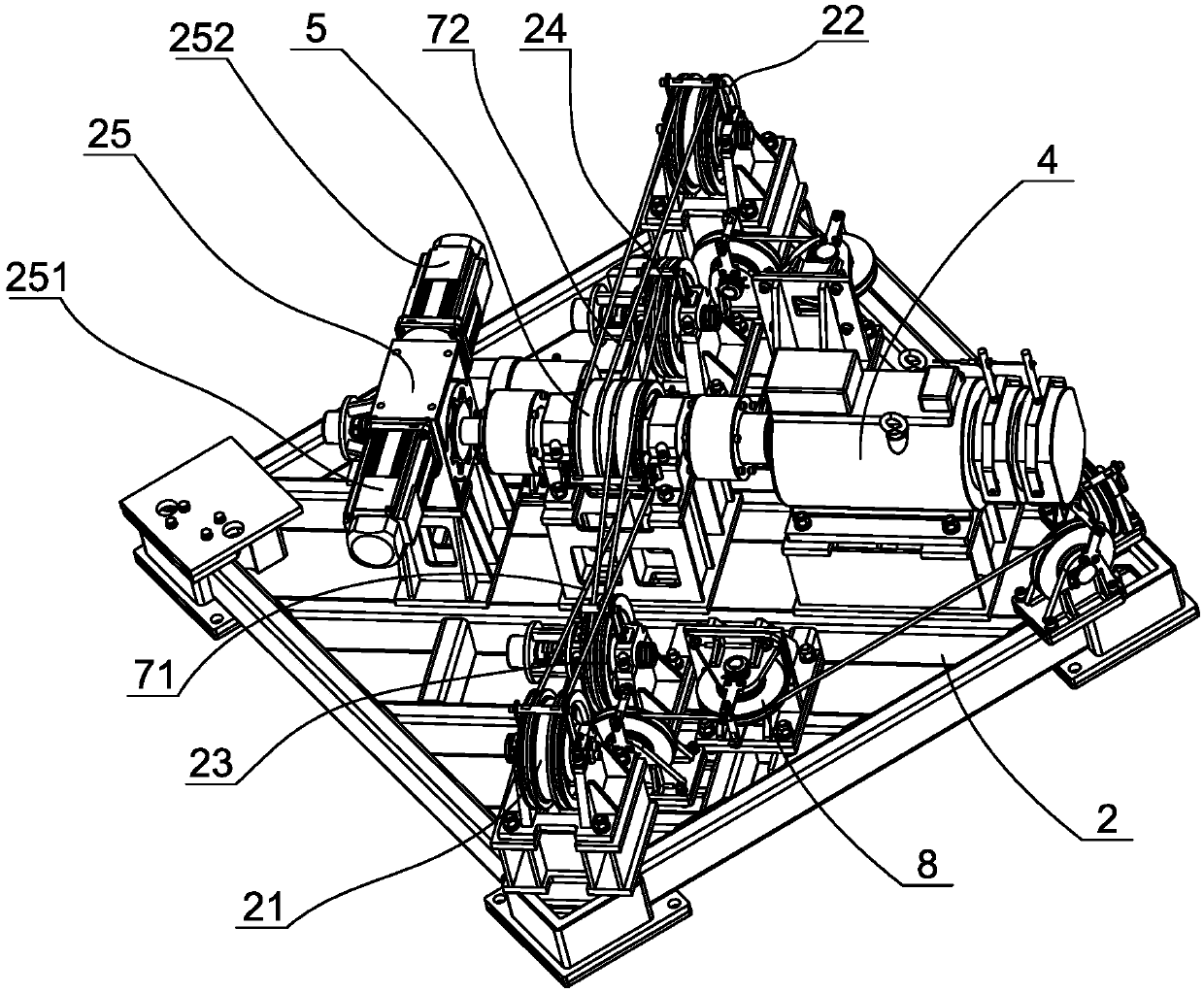
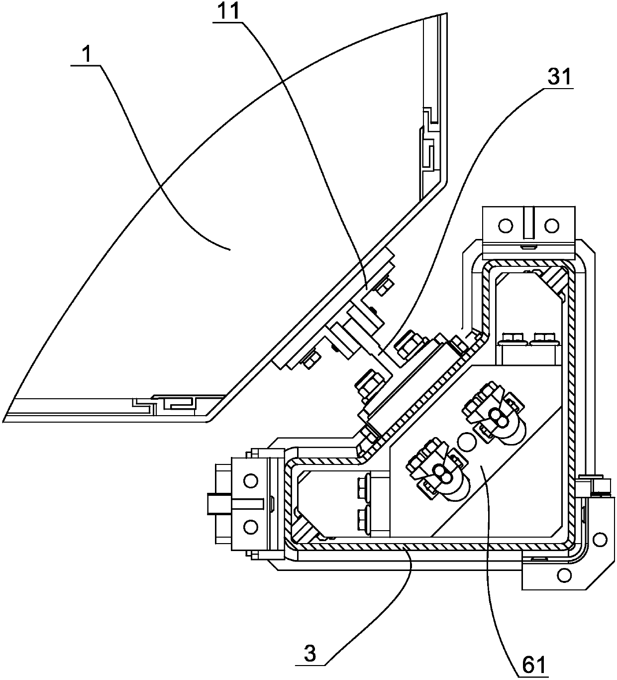
[0028] like figure 1 , figure 2 As shown, a counterweight arrangement structure in an elevator traction system includes a car 1, a rectangular installation platform 2, and hoistway columns 3 arranged at the four corners of the installation platform and extending vertically downward. A traction machine 4 and a traction wheel 5 coaxially connected with the traction machine are arranged on the platform. The hoistway column is made of extruded hollow structural profiles, thereby forming a vertical sliding cavity in the hoistway column. like image 3 As shown, guide rails 31 extending axially are arranged on the outside of the hoistway columns, and guide shoes 11 are respectively provided at the four corners of the car between the four hoistway columns, and the guide shoes are slidably connected to the corresponding guide rails. There is a trac...


PUM


Abstract

The invention discloses a counterweight arrangement structure in an elevator traction system. The counterweight arrangement structure comprises an elevator car, a mounting platform and shaftway vertical columns which are arranged at four corners of the mounting platform, a traction machine and a traction wheel connected with the traction machine are arranged on the mounting platform, a first traction rope and a second traction rope are wound around the traction wheel, one end of the first traction rope is connected with the top of the elevator car, the other end of the first traction rope is connected with a first counterweight which is slidably arranged in the first shaftway vertical column, one end of the second traction rope is connected with the top of the elevator car, the other end of the second traction rope is connected with a second counterweight which is slidably arranged in the other shaftway vertical column, the first counterweight and the second counterweight are located on the two sides of the traction wheel correspondingly, and the four corners of the elevator car are in sliding connection with the corresponding shaftway vertical columns correspondingly. According tothe counterweight arrangement structure, multi-direction free setting of an elevator car door is facilitated, meanwhile, the overall impression of an all-transparent sightseeing elevator and a household elevator can be remarkably improved, and the safety of the elevator can be improved.

Description

technical field [0001] The invention relates to the technical field of elevator manufacturing, in particular to a counterweight arrangement structure in an elevator traction system. Background technique [0002] In high-rise buildings, the elevator is a necessary accessory equipment, which can bring great convenience to the occupants. At present, with the development of the economy, a large number of middle and high-income groups have emerged, and the demand for villas is also increasing. Correspondingly, home elevators suitable for villa buildings have also become popular. The elevator mainly includes a shaft, a car that can be lifted and lowered in the shaft, and a drive mechanism for driving the car to go up and down. The traction machine is connected to the traction wheel, and a traction rope is wound around the traction wheel. One end of the traction rope is connected to the car, and the other end is connected to a counterweight that can be lifted and lowered in the ho...

Claims


Application Information

Patent Timeline
Patent Type & Authority Applications(China)
IPC IPC(8): B66B11/00B66B7/06B66B7/08B66B17/12
CPCB66B1/365B66B5/00B66B5/0018B66B5/0031B66B5/0037B66B5/005B66B5/0087B66B5/0093B66B5/021B66B5/027B66B5/028B66B5/04B66B5/044B66B5/08B66B5/16B66B5/22B66B5/26B66B7/02B66B7/06B66B7/08B66B9/00B66B11/0005B66B11/0035B66B11/0226B66B11/0293B66B11/04B66B11/0415B66B11/043B66B11/0446B66B11/08B66B13/12B66B13/125B66B13/165B66B17/12
Inventor 陈庆邓健李军
Owner SHAANXI SIUSAI ELECTROMECHANICAL TECH CO LTD
Why Eureka
Try Eureka