Torque limiter

a limiter and torque technology, applied in the direction of shafts and bearings, bearing components, slip couplings, etc., can solve the problems of affecting the transmission of torque from the input side to the output side, and affecting the performance of the bearing

Inactive Publication Date: 2001-03-27
SANKYO SEISAKUSHO
View PDF15 Cites 27 Cited by
  • Summary
  • Abstract
  • Description
  • Claims
  • Application Information

AI Technical Summary

Problems solved by technology

However, an excessive load generated from the torque limiter's output side will overcome the preload applied to the rollers with the result that the rollers are forced out of the concavities.
This action disengages the mechanical connection between the input and torque output parts, allows said parts to rotate independently, and thus interrupts the transmission of torque from the input to the output side.
This design results in a relatively complex bearing structure which necessitates that the torque limiter be fabricated to dimensions that are often larger than preferred.

Method used


Image

  • Torque limiter
  • Torque limiter
  • Torque limiter

Examples


Embodiment Construction

The following discussion provides a detailed explanation of the structure of the invention with reference to the attached figures.

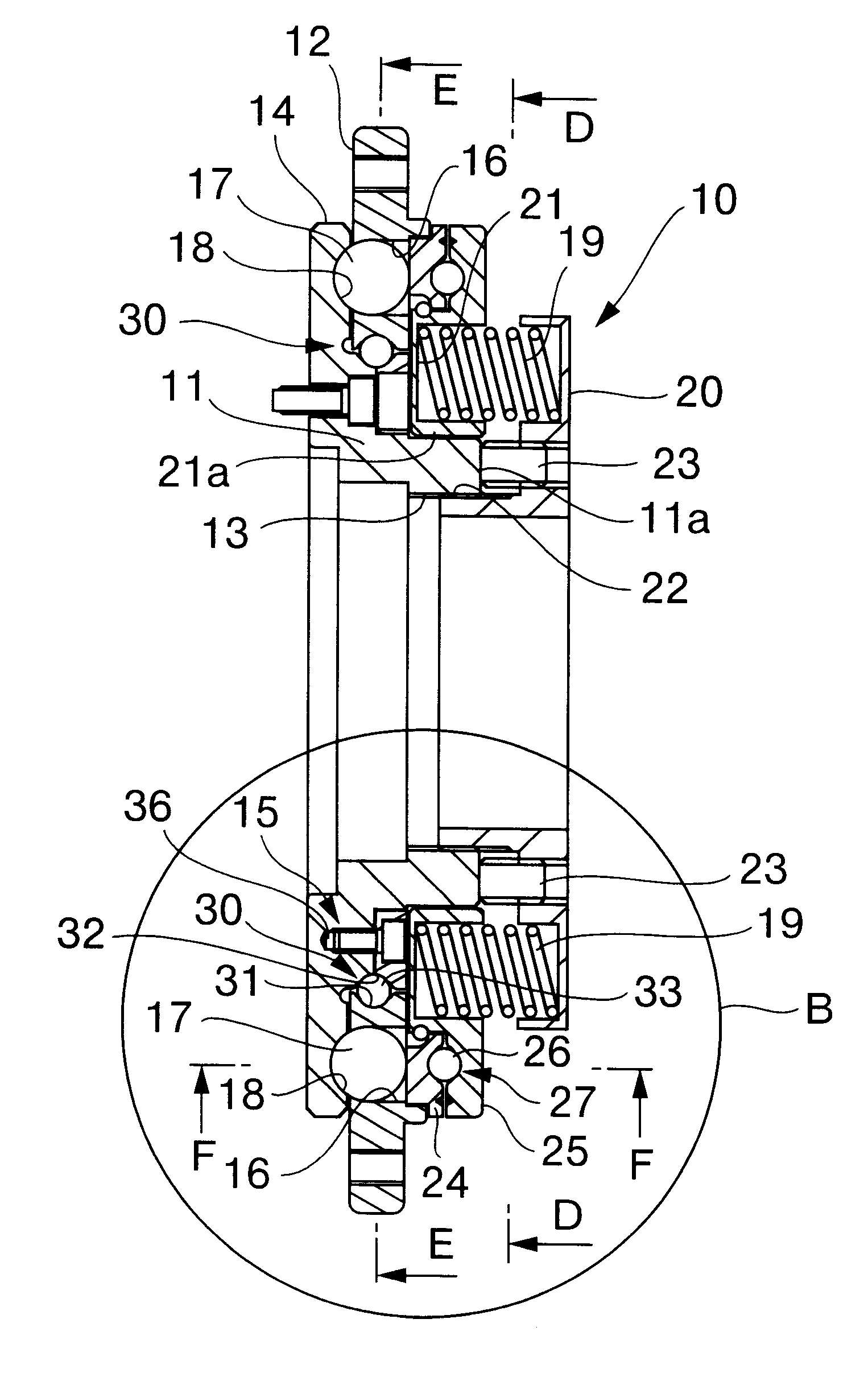
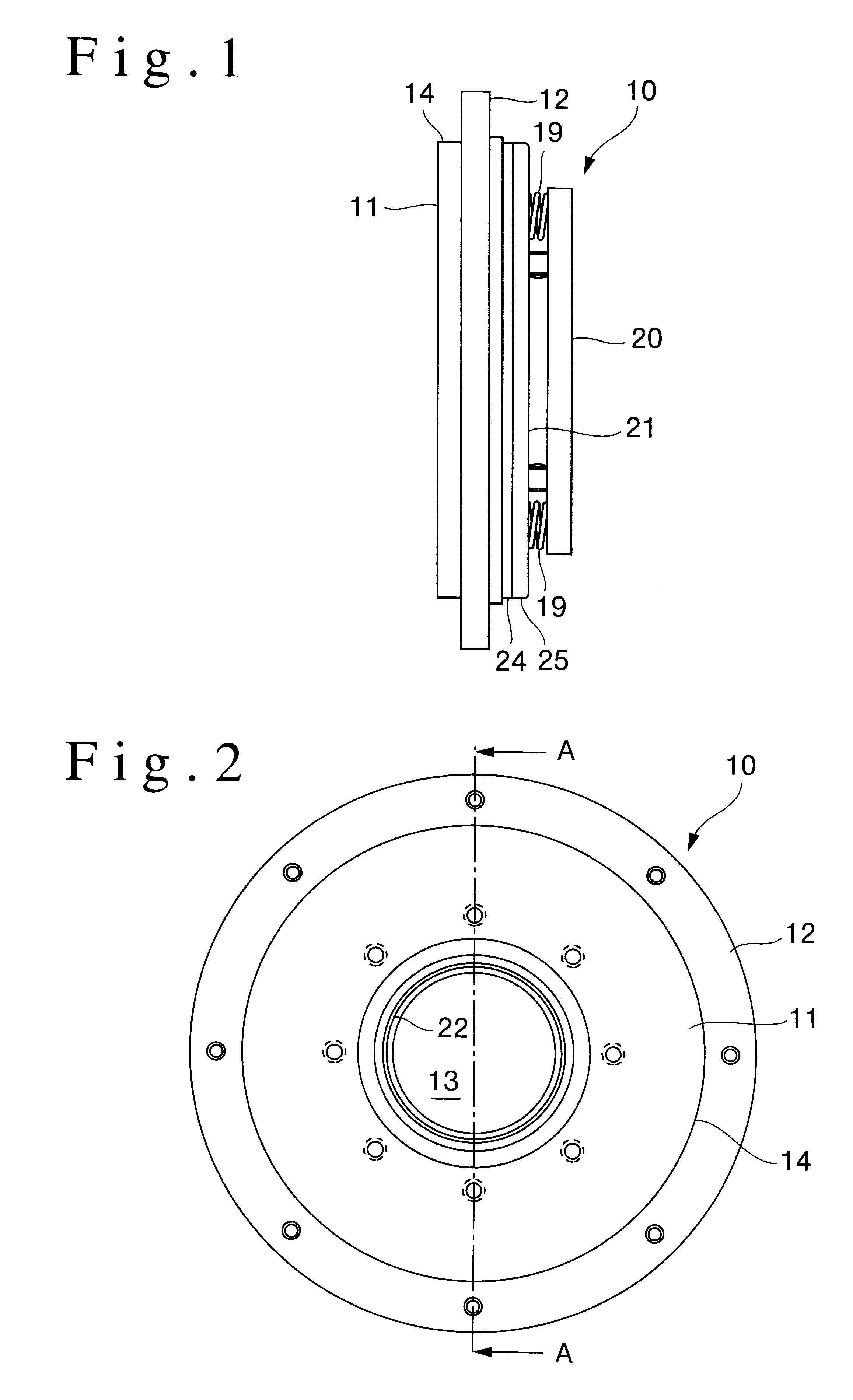
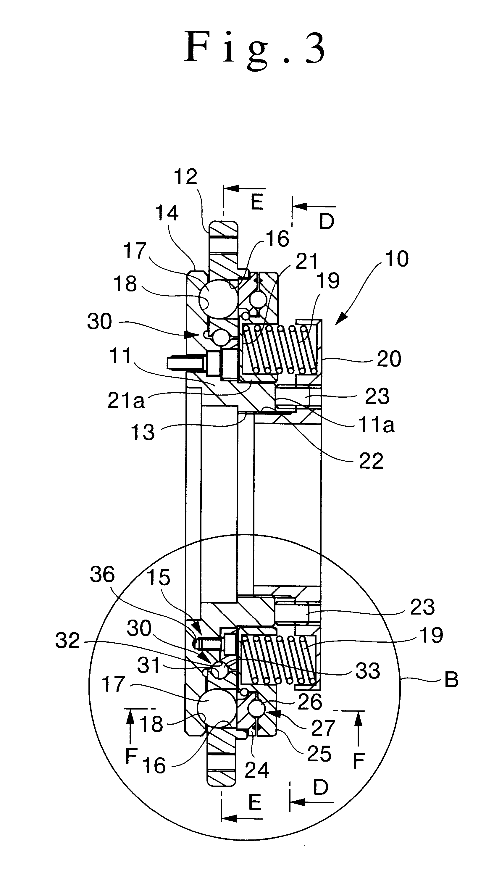
The main components of torque limiter 10 are boss 11 which operates as the aforesaid torque input part, and flange 12 which operates as the aforesaid torque output part; the aforesaid boss 11 and flange 12 being in mutually facing orientation and rotatable around the same axis. Boss 11 is of disc configuration, incorporates center hole 13 formed therein, and has flange 14 formed on its outer perimeter. Flange 12 is of ring configuration whose inner circumference encompasses a radial perimeter formed around the center of flange 14 as means of forming rotatable joint 15.

Multiple orifices 16, formed through flange 12 at non-uniform intervals on the same circumference, serve as means of maintaining torque balls 17 therein, said torque balls 17 serving as the aforesaid torque transmission part. Spheroid concavities 18 are formed on the face of flange 14 at loc...


PUM


Abstract

A torque limiting device capable of transferring torque within a power train, and also capable of disengaging the torque transfer connection when the torque level exceeds a specific point. A specific ball bearing joint is formed where a radial boss mates with the inner circumference of a flange. The ball bearing joint consists of an outer radial groove formed on the aforesaid inner circumference, an inner radial groove formed on the boss and facing the outer groove, and ball bearings inserted between the two radial grooves. Each radial groove is formed to a V-shape cross section having a radius of curvature smaller than that of the ball bearings, thus providing ball bearing support at two points within each groove, and four points of bearing support in total. Rotation of the torque output part is thus supported adequately in both the radial and axial thrust directions by a single ball bearing structure which allows the torque limiter to be made to compact dimensions.

Description

1. Field of the InventionThe invention relates to a torque limiter device capable of transferring torque from a power source to a driven device, and further capable of disengaging the torque transfer connection when an overload is encountered.2. Description of the Related ArtA torque limiter device has been put forth in Japanese unexamined patent publication No. 53-67407 (Int.Cl.F16D 7 / 06) and Japanese unexamined utility model publication No. 4-68228 (Int.Cl.F16D 43.20). This type of torque limiter is comprised of a torque input part connected to a torque generating power source, and a torque output part rotatably installed opposite to the aforesaid torque input part on the same shaft. A roller-type torque transmission device is installed between the aforesaid torque input and torque output parts in a manner as to allow the torque from the input side to be transferred to the output side without any power loss during normal operation. In the event that an excessive load is generated,...

Claims


Application Information

Patent Timeline
Patent Type & Authority Patents(United States)
IPC IPC(8): F16D7/00F16D7/08F16D7/06
CPCF16D7/08
Inventor KATO, HEIZABURO
Owner SANKYO SEISAKUSHO
Why Eureka
Try Eureka