Method and device for applying a surface structuring to a workpiece on a machine tool

a surface structure and workpiece technology, applied in the field of face milling method, can solve the problems of inability to apply surface structure with the desired image quality, inability to transfer pulse-shaped voltage signals by inductive, signal is highly distorted, etc., to achieve improved energy transfer or signal transfer, small and compact dimensions, and improved image quality of applied patterns

Active Publication Date: 2020-02-25
SAUER GMBH
View PDF11 Cites 1 Cited by
  • Summary
  • Abstract
  • Description
  • Claims
  • Application Information

AI Technical Summary

Benefits of technology

In order to avoid the above described drawbacks of the previously known method for applying a surface structuring to a surface of a workpiece, an object of the present invention is to provide an improved method for applying a surface structuring to a surface of a workpiece, which can be realized with smaller and more compact dimensions of the tool, tool holder and / or tool head and with an improved energy transfer or signal transfer and better image quality of the applied pattern.
According to a useful preferred embodiment of the invention, the actuator comprises one or more piezo elements, in particular a stack of a plurality of plate-shaped piezo elements. For example, the actuator can be made in a particularly simple and reliable way.

Problems solved by technology

Furthermore, the necessary pulse-shaped voltage signals cannot be transferred by an inductive or contactless energy or signal transfer since, owing to the inductivities, the signal is always influenced.
If short pulse sequences having a low frequency (about 1 to 5 kHz) are inductively transmitted, the signal is highly distorted in a disadvantageous manner on account of the high inductivities, such that the pattern or the surface structuring cannot be applied with the desired image quality.
However, if slip rings are used for the signal transfer while contact is made, this is disadvantageous in industrial practice, in particular on account of the maintenance susceptibility resulting from wear and contamination.
Therefore, the prior art methods show the drawbacks of a large (and thus inconveniently dimensioned) tool head and of an energy transfer which is wire-bound (or realized by slip rings).

Method used


Image

  • Method and device for applying a surface structuring to a workpiece on a machine tool
  • Method and device for applying a surface structuring to a workpiece on a machine tool
  • Method and device for applying a surface structuring to a workpiece on a machine tool

Examples


Embodiment Construction

Examples and embodiments of the present invention are described in detail below with reference to the enclosed drawings. The same and similar elements in the drawings can here be designated with the same reference signs, but sometimes also with different reference signs.

However, it should be noted that the present invention is by no means limited or confined to the below described embodiments and the design features thereof, but also comprises modifications of the embodiments, in particular those which are included by modifications of the features of the described examples and / or by combining individual or a plurality of the features of the described examples within the scope of protection of the independent claims.

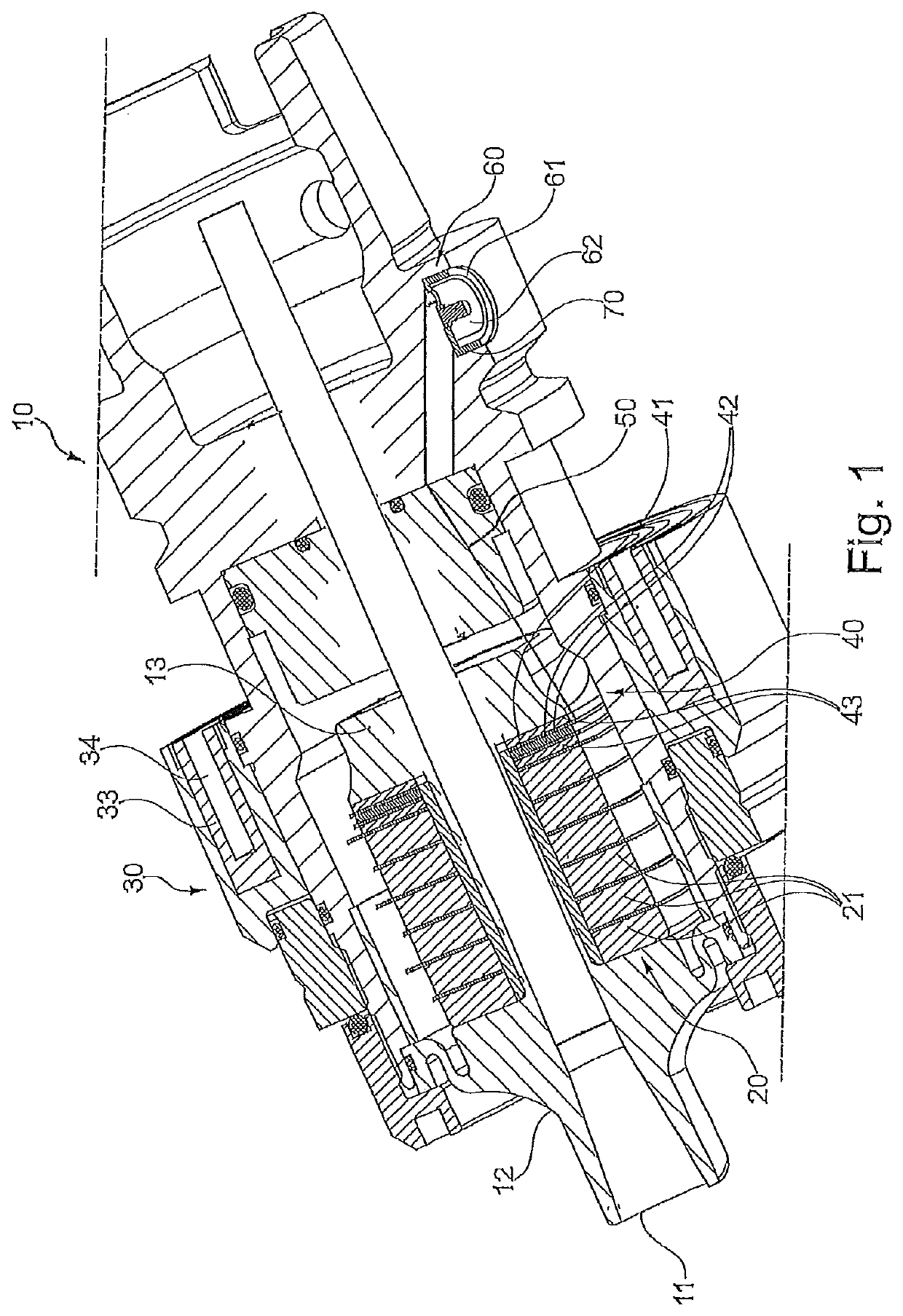
FIG. 1 shows an exemplary design of a tool holder 10 (tool head) which can be used in the method according to the invention.

One end of the tool holder 10 has a tool receiving portion 11 for receiving a tool 90 (not shown in FIG. 1). The tool holder 10 accommodates e.g. a ...


PUM

PropertyMeasurementUnit
frequencyaaaaaaaaaa
frequencyaaaaaaaaaa
frequencyaaaaaaaaaa

Abstract

A method and a device applying surface structuring to a surface of a workpiece on a machine tool, performing a feed motion of a milling cutter which is rotationally driven by a work spindle of the machine tool, received in a tool head of the machine tool and has at least one protruding cutting edge along the surface of the workpiece; applying the surface structuring in accordance with a predetermined pattern to the surface of the workpiece during the feed motion of the milling cutter on the basis of a control signal to an actuator which is integrated in the tool head and is configured to drive a vibration of the milling cutter on the basis of the control signal, wherein the control signal contains high-frequency carrier signal and a useful signal which modulates the carrier signal and which is generated on the basis of data indicating the predetermined pattern.

Description

The present invention relates to a method for applying a surface structuring to a surface of a workpiece on a machine tool. The present invention also relates to a device and a machine tool, on which the above mentioned method can be carried out. Furthermore, the present invention relates to a computer program product which can be used to carry out the above mentioned method.BACKGROUND OF THE INVENTIONDE 10 2012 002 140 B4 discloses a method of the generic type, in particular a face milling method, for applying a surface structuring to a surface of a workpiece. Such a surface structuring or marking of the surface can serve e.g. for decorative purposes or for coding the component or workpiece by applying e.g. an image pattern and / or text pattern to the surface of the workpiece.Here, a milling cutter or a face-milling cutter can be used on a machine tool, said cutter having e.g. an axially protruding cutting edge that is not disposed in the tool axis and rotates when the tool is rotat...

Claims


Application Information

Patent Timeline
Patent Type & Authority Patents(United States)
IPC IPC(8): B23B29/12B24B1/04H03K5/01
CPCB23B29/125B24B1/04H03K5/01B23C3/13B23C9/00B23Q11/00B23Q17/22G05B19/4097B23C3/00B23Q15/013G05B19/4166B23C2220/48B23C2270/10
Inventor KETELAER, JENS
Owner SAUER GMBH
Why Eureka
Try Eureka