Burner, method for operating a burner and gas turbine

a burner and gas turbine technology, applied in the field of combustion engines, can solve the problems of significant noise exposure and damage, insufficient measurement in all operating states, and relatively high measurement costs, so as to reduce the fluctuation of air ratios, reduce the noise of combustion oscillations, and reduce the effect of acoustic disturbances

Inactive Publication Date: 2008-01-22
SIEMENS ENERGY GLOBAL GMBH & CO KG
View PDF18 Cites 27 Cited by
  • Summary
  • Abstract
  • Description
  • Claims
  • Application Information

AI Technical Summary

Benefits of technology

[0012]The invention demonstrates, for the first time, a means not only for attenuating a combustion oscillation by means of a Helmholtz resonator, but also for preventing a significant reason for the occurrence of the combustion oscillation: namely the fluctuations in the air ratio. As a result of the temporally inhomogeneous heat release, the air ratio fluctuation causes acoustic pulses which can cause a feedback and the formation of a combustion oscillation in the manner described above. Because the Helmholtz resonator is now arranged downstream of the fuel inlet, acoustic disturbances at the fuel inlet position and therefore air ratio fluctuations are reduced. In addition to the mere absorption of vibrational energy, the Helmholtz resonator at this resonator position is therefore already capable of preventing the occurrence of the combustion oscillation. A much more efficient means for countering combustion oscillations is achieved thereby.
[0021]The Helmholtz resonator preferably has a resonator volume and is connected to the combustor channel via a resonator port, wherein the resonator port extends into the resonator volume by means of a small tube. Furthermore, a plurality of small tubes preferably project into the resonator volume. The internal volume of the resonator is hardly changed in this case. The external dimensions of the resonator can therefore be kept small. The small tubes can be designed such that they are twisted in this case, thus ensuring adequate distance relative to the walls. By changing the length of the small tubes, the attenuation apparatus can be adjusted to various frequencies which occur in the combustion system. In this case, it is not necessary to change the external dimensions of the resonator, and hence of the combustion insert, or the open overall cross-sectional area. The main advantage: in order to attenuate low frequencies, it is possible to forgo an increase in the volume of the resonator by virtue of the inwardly projecting small tubes.

Problems solved by technology

Such an amplified combustion oscillation can result in significant noise exposure and damage due to vibrations.
However, it is also apparent that this measure is not sufficient in all operating states, since combustion oscillations can still occur when oscillations in the fuel line are suppressed.
In terms of equipment, however, this measure is relatively expensive in comparison with the purely passive measure of using Helmholtz resonators.

Method used


Image

  • Burner, method for operating a burner and gas turbine
  • Burner, method for operating a burner and gas turbine
  • Burner, method for operating a burner and gas turbine

Examples


Embodiment Construction

[0032]Identical reference signs have the same meaning in the different figures.

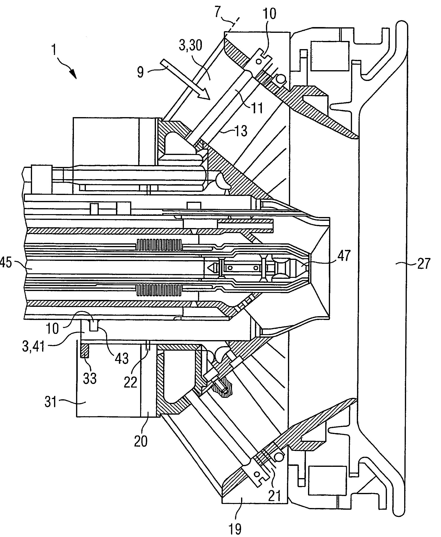
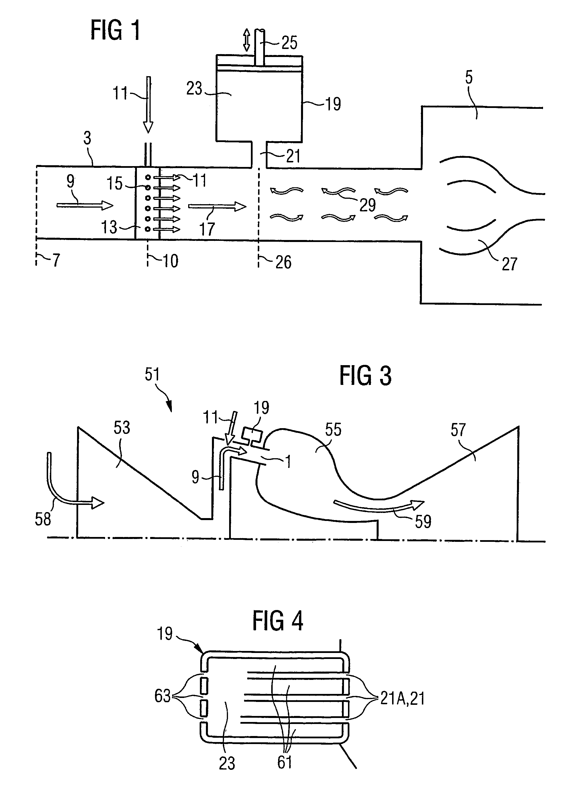
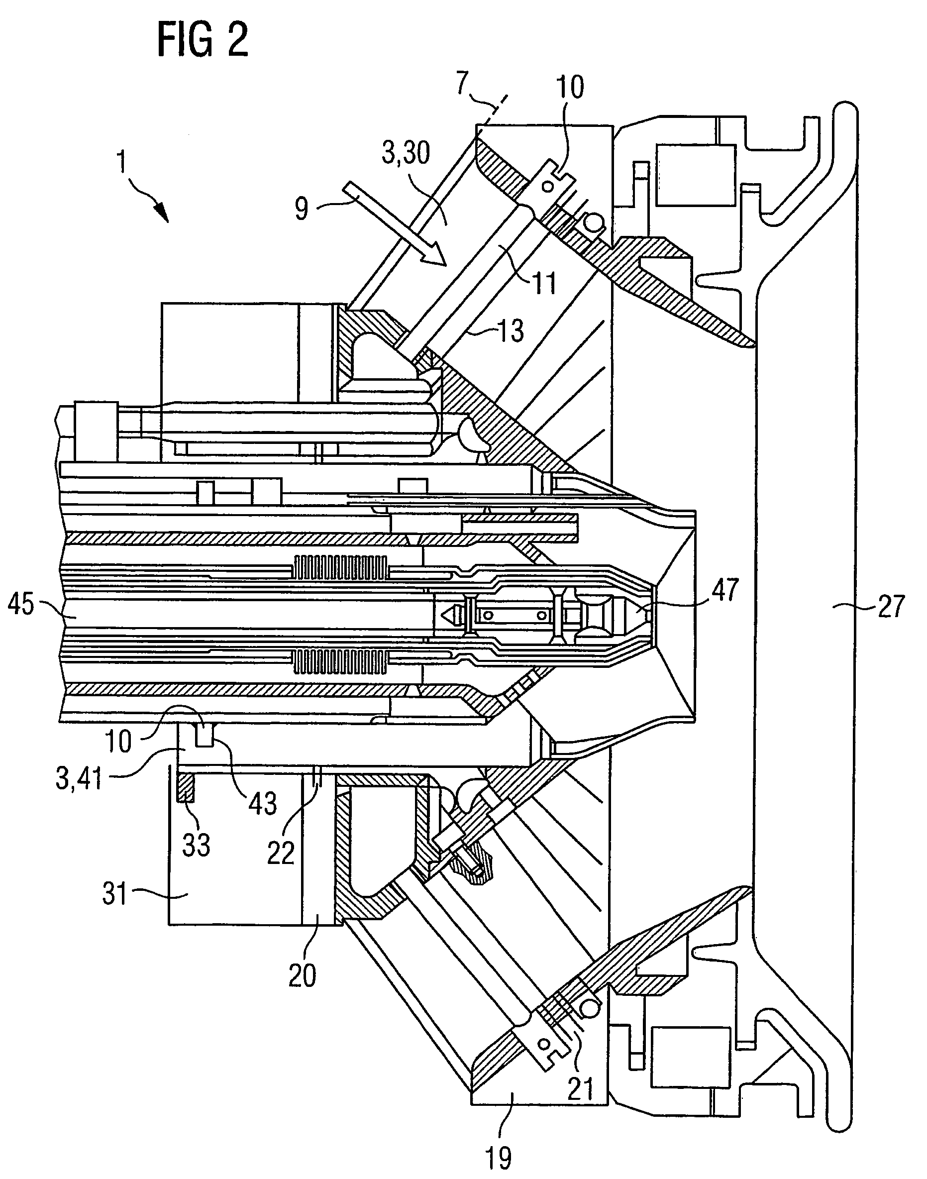
[0033]FIG. 1 schematically shows a combustor 1 and a method for operating the combustor 1. The combustor 1 has a combustor channel 3. The combustor channel 3 flows into a combustion chamber 5. Combustion air 9 is introduced into the combustor channel 3 at an air inlet position 7. Fuel 11, in particular natural gas, is introduced into the combustor channel 3 at a fuel inlet position 10 which is located downstream of the air inlet position 7. This occurs via outlet openings 15 in twisted blades 13, which are arranged in the combustor channel 3 and produce a stabilization of the combustion by generating a backflow area. The resulting mixture 17 of combustion air 9 and fuel 11 is then burned in the combustion chamber 5.

[0034]A Helmholtz resonator 19 is directly connected via a resonator port 21 to the flow of the combustor channel 3 at a resonator position 26. The Helmholtz resonator 19 has a resonator volume...


PUM


Abstract

This invention relates to a burner, especially a gas turbine burner, wherein a Helmholtz resonator downstream of a fuel inlet position in directly linked with a burner channel. In this manner, combustion oscillations do not arrive at the fuel inlet position, thereby reducing acoustic disturbances and air ration deviations which are the main cause for the formation of combined oscillations. The invention also relates to a method for operating a burner and a gas turbine.

Description

CROSS REFERENCE TO RELATED APPLICATION [0001]This application is the U.S. National Stage of International Application No. PCT / EP03 / 02079, filed Feb. 28, 2003 and claims the benefit thereof. The International Application claims the benefits of European Patent application No. 02005136.3 EP filed Mar. 7, 2002, both of the applications are incorporated by reference herein in their entirety.FIELD OF THE INVENTION [0002]The invention relates to a combustor having a combustor channel into which combustion air can be introduced at an air inlet position and fuel can be introduced at a fuel inlet position, wherein the fuel inlet position is located downstream of the air inlet position, and wherein the combustion air and the fuel can be mixed in the combustor channel and then discharged into a combustion zone. The invention also relates to a method for operating such a combustor and a gas turbine, in particular a gas turbine which has an annular combustion chamber.BACKGROUND OF THE INVENTION [...

Claims


Application Information

Patent Timeline
Patent Type & Authority Patents(United States)
IPC IPC(8): F02C7/045F23R3/14F23D1/00F23M20/00F23R3/28
CPCF23R3/14F23R3/286F23R2900/00014F23M20/005Y02T50/60
Inventor FLOHR, PATRICKKREBS, WERNERSCHULZE, GÜNTHER
Owner SIEMENS ENERGY GLOBAL GMBH & CO KG
Why Eureka
Try Eureka