Clamp locking mechanism in device for welding plastic tubes

a technology of plastic tube and locking mechanism, which is applied in the direction of auxillary welding device, soldering apparatus, manufacturing tools, etc., can solve the problems of weak welds, weak welds, and weak welds, and achieves the effect of defeating the purpose of the latter

Active Publication Date: 2011-11-29
GENESIS BPS
View PDF42 Cites 5 Cited by
  • Summary
  • Abstract
  • Description
  • Claims
  • Application Information

AI Technical Summary

Benefits of technology

[0004]A further object of this invention is to provide such a device which incorporates a clamp locking mechanism which in cooperation with the spring effectively maintains the clamp faces flush when the tubing is compressed during loading.
[0006]The clamp locking mechanism may include a handle mounted on the lever arm shaft to facilitate the movement of the lever arm. A support bracket mounted to a cam roller guide block prevents the lever arm from moving backwards when the tube clamps are under compressive loads and are pushing against the pivot arm.

Problems solved by technology

If, however, a tubing of greater tube thickness is used, the spring force may not be sufficient to keep the clamp faces flush when the tubing is compressed during loading.
In such circumstance this would defeat the purpose of the later stripping process and could create conditions for weak welds.

Method used


Image

  • Clamp locking mechanism in device for welding plastic tubes
  • Clamp locking mechanism in device for welding plastic tubes
  • Clamp locking mechanism in device for welding plastic tubes

Examples


Embodiment Construction

[0015]The present invention is directed to devices for welding plastic tubes, such as disclosed in U.S. Pat. No. 7,398,813 and in the patents referred to in column 1 of U.S. Pat. No. 7,398,813. All of the details of U.S. Pat. No. 7,398,813 and the other patents referred to therein are incorporated herein by reference thereto.

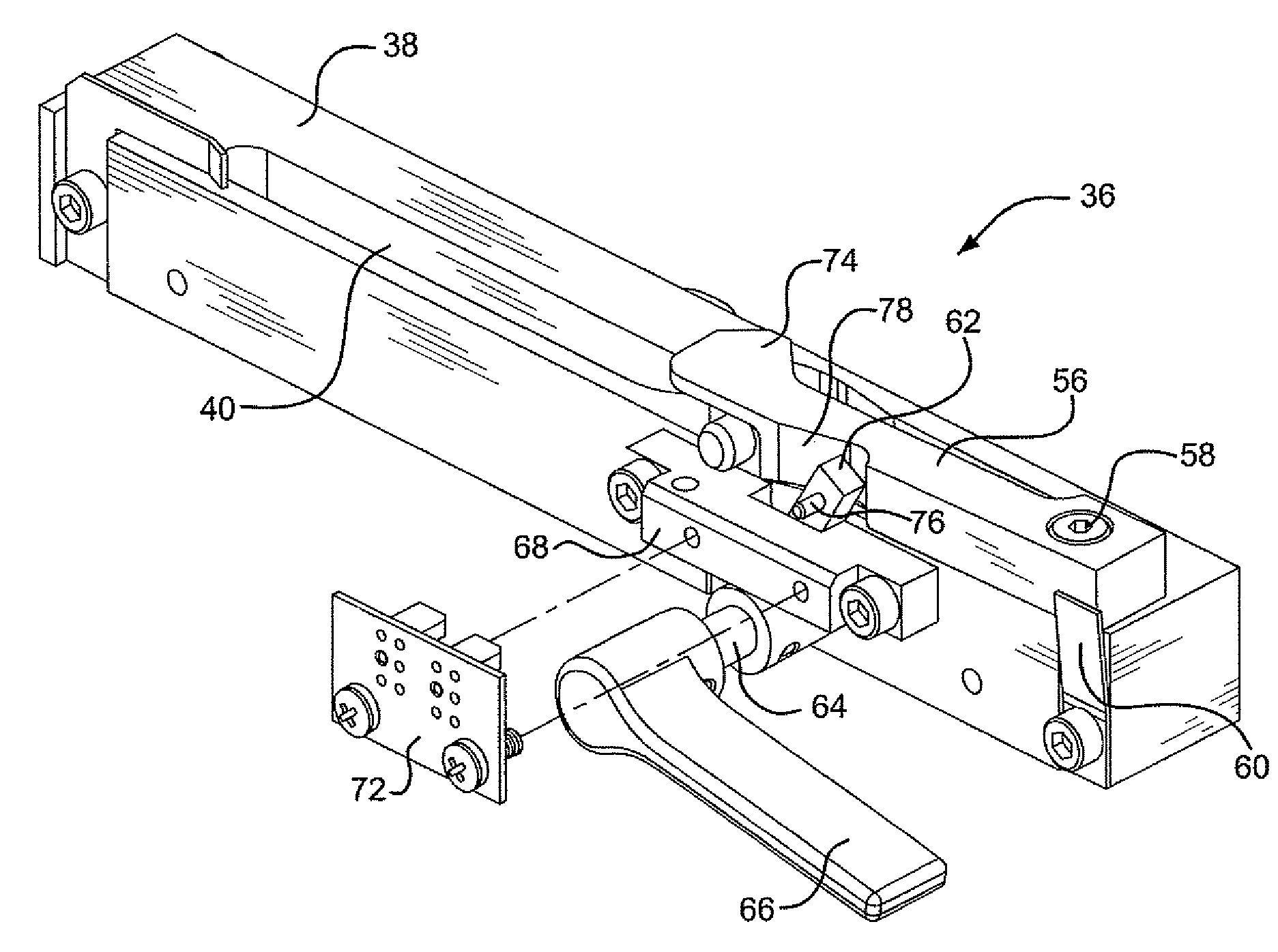
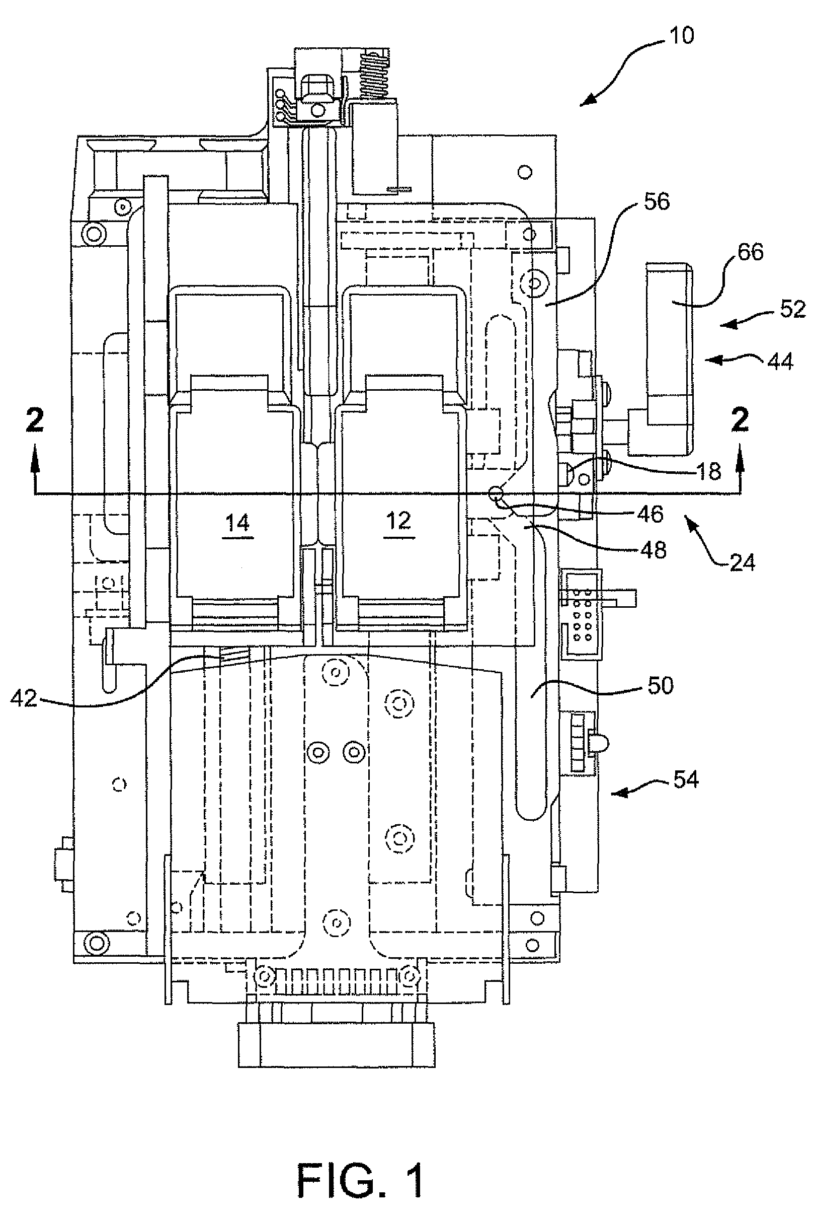
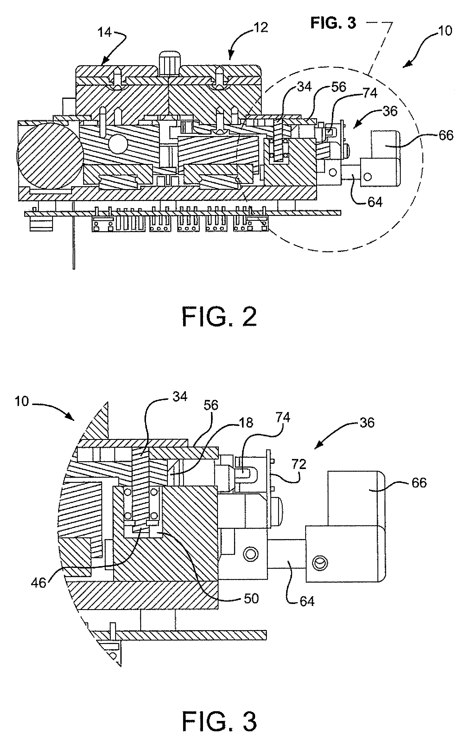
[0016]FIGS. 1-3 and 6 illustrate a device 10 for welding plastic tubes. As shown in FIG. 1 device 10 includes a first tube holder 12 and a second tube holder 14. Tube holder 12 includes first tube holding area 16 (FIG. 6) and a parallel second tube holding area. The tube holding areas may be grooves extending across the tube holder. Similarly, second tube holder 14 includes first tube holding area 20 and second tube holding area which is parallel to tube holding area 20. These tube holding areas may also be grooves. The spacing between the tube holder areas in the tube holder 12 is the same as the spacing between tube holding areas in tube holder 14.

[0017]FIG. 1...


PUM

PropertyMeasurementUnit
forceaaaaaaaaaa
movementaaaaaaaaaa
areasaaaaaaaaaa

Abstract

A device for welding plastic tubes includes a laterally movable tube holder having tube holding areas and a laterally fixed tube holder having tube holding areas. Each tube holder includes clamping structure for clamping each tube placed in the respective tube holder areas and for creating a fluid free area. A spring mechanism urges the laterally movable tube holder toward the laterally fixed tube holder to maintain the clamp faces flush against each other. A clamp locking mechanism is provided to supplement the action of the spring mechanism by maintaining the clamp faces flush against each other during the loading of the tubes.

Description

BACKGROUND OF THE INVENTION[0001]Various techniques have been used for welding plastic tubes particularly as used in the medical field. U.S. Pat. No. 7,398,813 describes a device having a first tube holder and a second tube holder. Each of the tube holders has first and second parallel tube holding areas in line with each other. In practice a first tube would be placed in the aligned first tube holding areas across the location where the tube holders are adjacent each other. A second tube would be similarly placed in the aligned second tube holding areas. A tube clamp in each of the first tube holding areas clamps the first tube to create a generally fluid free area of the first tube. A tube clamp is similarly provided in the second tube holding areas to create a generally fluid free area of the second tube. One of the tube holders is laterally movable while the clamps are maintained in their clamping condition. To increase the length of the fluid free area, the laterally movable tu...

Claims


Application Information

Patent Timeline
Patent Type & Authority Patents(United States)
IPC IPC(8): B23Q3/18
CPCB23K37/0435B29C65/14B29C65/7802B29C66/1142B29C66/5221B29C66/857B29C66/8227B29C66/8226B29C65/00B29C65/1412B29C2035/0822B29C2793/0081B29C66/73921
Inventor IVANSONS, IVARS V.SPENCER, DUDLEY W. C.
Owner GENESIS BPS
Why Eureka
Try Eureka