Hose handling apparatus

a technology of hoses and handling devices, applied in electrical devices, load-engaging elements, cell components, etc., can solve the problems of difficult holding on to, unable to position the hose, and difficult to grasp or maneuver the high-pressure hose on the outside surface of the hose,

Inactive Publication Date: 2011-11-29
PADILLA WILLIAM
View PDF14 Cites 2 Cited by
  • Summary
  • Abstract
  • Description
  • Claims
  • Application Information

AI Technical Summary

Benefits of technology

[0008]The hose handling apparatus and method disclosed herein addresses the above stated needs for handling a hose with an improved grip. The hose handling apparatus disclosed herein enables a user to grip, advance, and maneuver the hose without difficulty. The term “user” as used herein refers to a person, for example, a firefighter, using the hose handling apparatus.
[0011]The handle, the first gripping element, and the second gripping element form a parallel configuration which is perpendicular to a planar surface of the support member. Each of the first gripping element and the second gripping element comprises a concaved mid-section for firmly positioning and securing the hose. The first gripping element and the second gripping element grip the hose positioned between them firmly. A pair of generally circular washers, herein referred to as “washers”, made of a flexible material is provided around the first gripping element and the second gripping element to render a firm grip to the hose and to prevent abrasion of the hose.
[0012]The hose handling apparatus further comprises a locking assembly that secures the hose between the first gripping element and the second gripping element to prevent the hose from sliding off from the hose handling apparatus while maneuvering the hose. The hose handling apparatus further comprises an elongated slot provided on the middle section of the support member along a longitudinal axis of the support member to facilitate slidable movement, positioning and attachment of the first gripping element with respect to the second gripping element along the elongated slot for accommodating hoses of different sizes.
[0013]In another embodiment, the first gripping element is fixed and the second gripping element is rollable. In this embodiment, the hose handling apparatus comprises a spindle detachably connected to and substantially perpendicular to the support member at the second end of the support member to form a rigid connection with the support member. The second gripping element is rollably connected and coaxial to the spindle. The second gripping element rotates about a longitudinal axis common to both the second gripping element and the spindle for enabling the hose positioned between the fixed first gripping element and the rollably connected second gripping element to roll smoothly on the rollably connected second gripping element. The fixed first gripping element supports the top portion of the hose and the rollably connected second gripping element supports the bottom portion of the hose, thereby facilitating the hose to roll smoothly on the rollably connected second gripping element without dragging on the rollably connected second gripping element.

Problems solved by technology

Handling these high pressure hoses with a user's hand is difficult.
Furthermore, a high pressure hose is difficult to grasp or maneuver when the outside surface of the hose is wet, for example, when the hose is exposed to water from rain, or water discharged from the hose.
Firefighters also find it difficult to hold on to, or position the hose due to the back pressure exerted on the hose as the high pressure water is discharged from the hose.
Furthermore, maneuvering the high pressure hose to different positions and moving the hose is difficult.

Method used


Image

  • Hose handling apparatus
  • Hose handling apparatus
  • Hose handling apparatus

Examples


Embodiment Construction

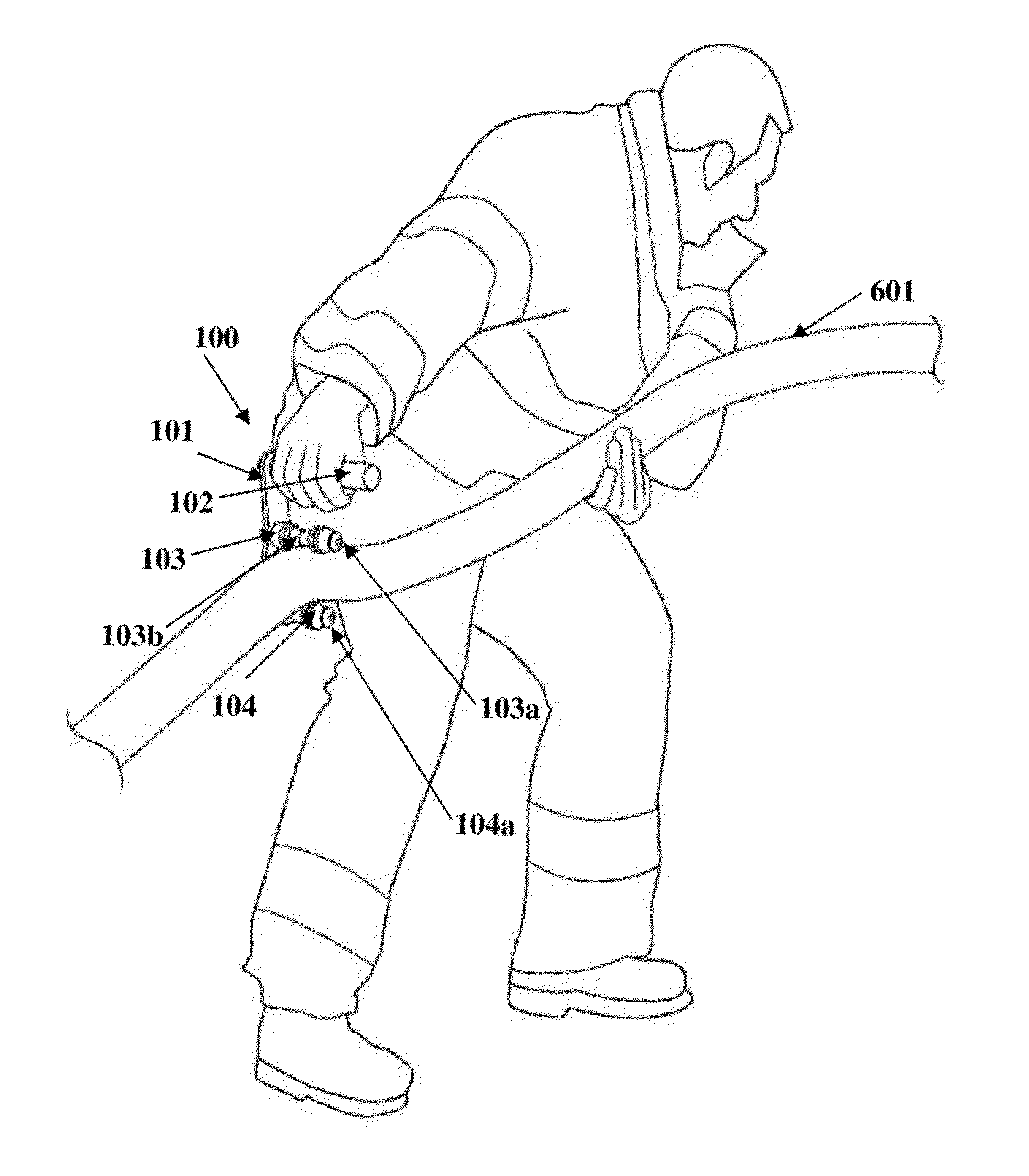
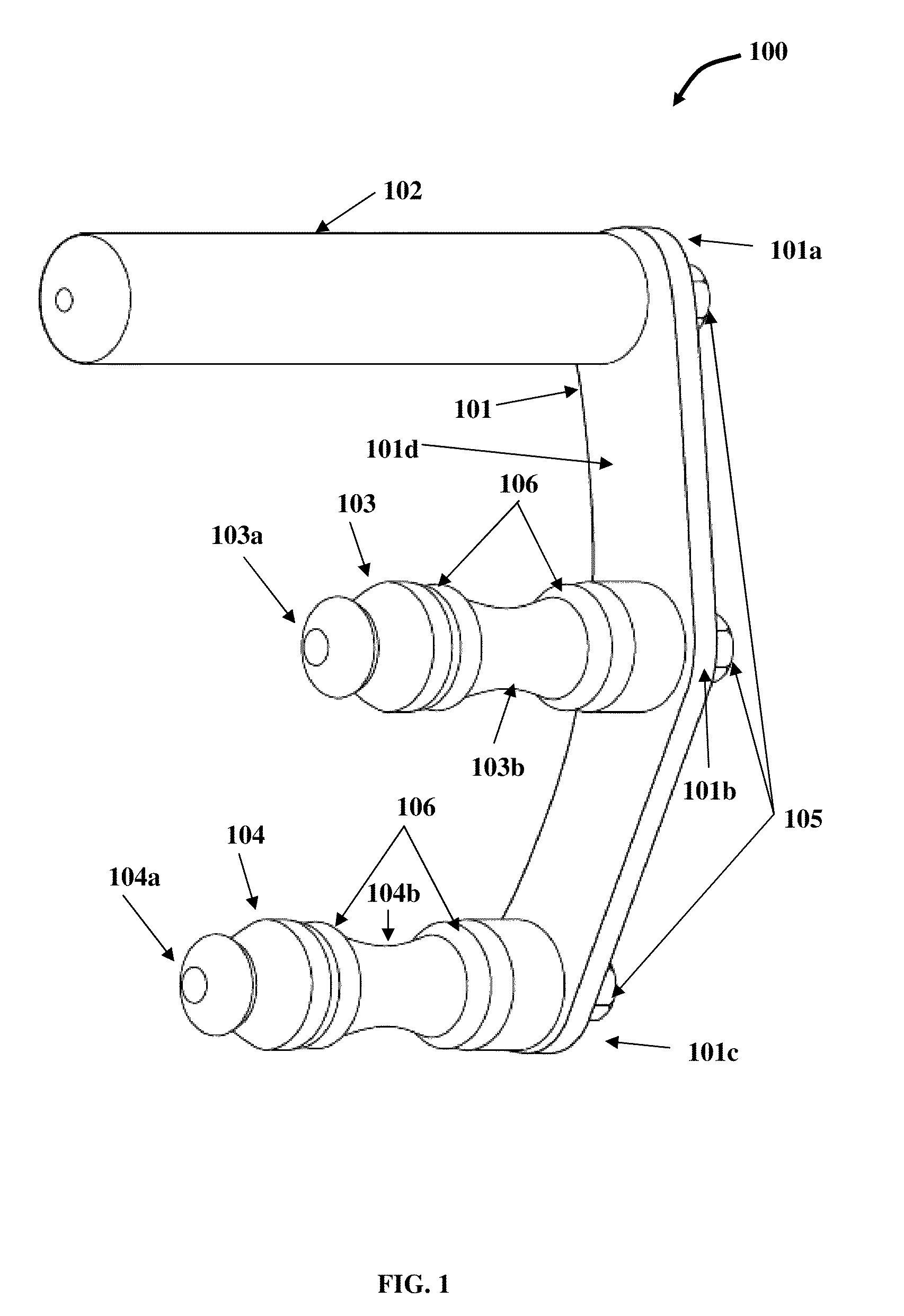
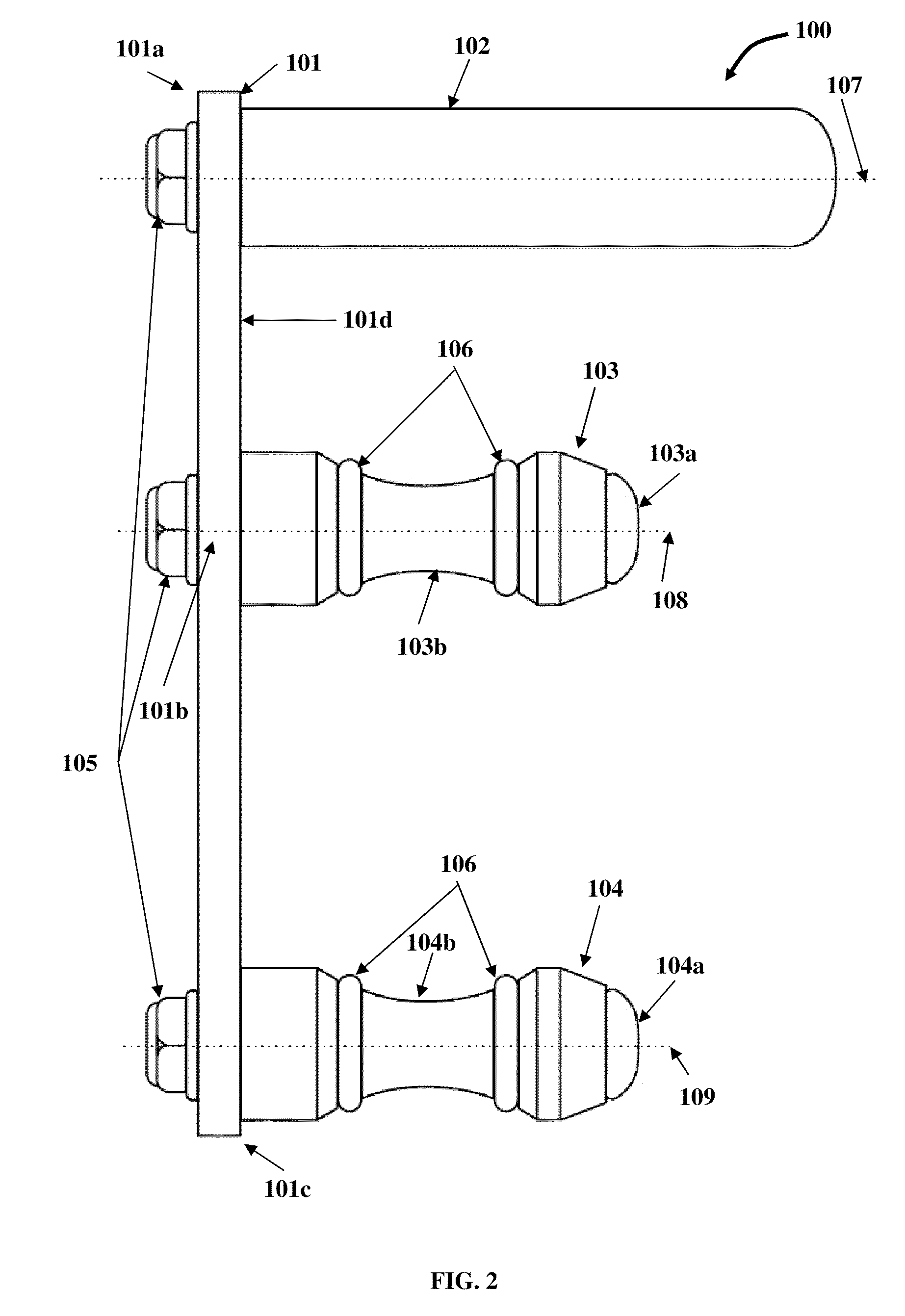
[0027]FIG. 1 exemplarily illustrates a perspective view of a hose handling apparatus 100 comprising a support member 101, a generally cylindrical handle 102, a first generally cylindrical curvilinear gripping element 103, and a second generally cylindrical curvilinear gripping element 104. Herein, the generally cylindrical handle 102 is referred to as a “handle”, the first generally cylindrical curvilinear gripping element 103 is referred to as a “first gripping element”, and the second generally cylindrical curvilinear gripping element 104 is referred to as a “second gripping element”. The hose 601 referred to herein is, for example, a high pressure hose as exemplarily illustrated in FIG. 6.

[0028]The support member 101 comprises a first end 101a, a second end 101c, and a middle section 101b defined by the section between the first end 101a and the second end 101c. The support member 101 is angled at its middle section 101b. The handle 102 is detachably connected to and substantiall...


PUM


Abstract

A hose handling apparatus for gripping, advancing, and maneuvering a high pressure hose is provided. The hose handling apparatus comprises a support member comprising a first end, a middle section, and a second end, a generally cylindrical handle detachably connected to and substantially perpendicular to the first end of the support member forming a rigid connection with the support member to provide grip to a user's hand, a first generally cylindrical curvilinear gripping element detachably connected to and substantially perpendicular to the middle section of the support member, and a second generally cylindrical curvilinear gripping element detachably connected to and substantially perpendicular to the second end of the support member. The support member is angled at the middle section. The handle and the gripping elements form a parallel configuration which is perpendicular to a planar surface of the support member. The gripping elements grip the hose positioned between them firmly.

Description

CROSS REFERENCE TO RELATED APPLICATIONS[0001]This application claims the benefit of the following provisional patent applications:[0002]1. Provisional patent application No. 61 / 103,644 titled “Hose Handling Apparatus”, filed on Oct. 8, 2008 in the United States Patent and Trademark Office.[0003]2. Provisional patent application No. 61 / 147,474 titled “Hose Handling Device”, filed on Jan. 27, 2009 in the United States Patent and Trademark Office.The specification of the above two referenced applications are incorporated herein by reference in their entirety.BACKGROUND[0004]A hose is a flexible tube used for conveying liquids or gases under pressure. The shape of a hose is typically cylindrical. Hoses are made of different materials, for example, nylon, polyurethane, polyethylene, neoprene, canvas, or rubber based on the environment and pressure rating. Hoses are used in gardening, firefighting, underwater diving, agriculture, industries, hydraulics, chemical engineering, and construct...

Claims


Application Information

Patent Timeline
Patent Type & Authority Patents(United States)
IPC IPC(8): B65G7/12A62C33/00
CPCA62C33/04B65G7/12
Inventor PADILLA, WILLIAM
Owner PADILLA WILLIAM
Why Eureka
Try Eureka