Method to test a brake of a robot

a robot and brake technology, applied in the direction of force/torque/work measurement apparatus, instruments, manufacturing tools, etc., can solve the problems of large motor torque and inapplicability of the electric motor

Active Publication Date: 2011-12-06
KUKA LAB GMBH
View PDF12 Cites 26 Cited by
  • Summary
  • Abstract
  • Description
  • Claims
  • Application Information

AI Technical Summary

Benefits of technology

[0006]It is an object of the present invention to provide a more flexible method for testing a brake of a robot.
[0025]According to this variant of the method according to the invention, the breakaway torque of the brake can be determined in that on the one hand the actuator generates an actuator torque that is greater than the braking torque applied by the brake. Moreover, a movement of the axis (caused in particular by the actuator torque) is mechanically prevented in that the axis is, for example, mechanically arrested or—for this variant of the method according to the invention—the axis is brought into a mechanical end stop of the robot that is provided for said axis so that the actuator cannot move the axis further. In that the actuator torque applied by the actuator is greater than the braking torque to be applied by the brake, an output torque acts on the axis, which is in turn determined by the torque sensor. A conclusion about the braking torque can in turn be drawn based on the evaluation of the actuator torque and the torque determined by means of the torque sensor, and thus the functional capability of the brake can be assessed. Depending on the mechanical prevention of the movement of the axis, the braking torque applied by the brake corresponds less to the actuator torque than the torque determined by means of the torque sensor. A torque acting on the axis due to the force of gravity must possibly still be taken into account. The actuator torque applied by the actuator can, for example, be determined via an electrical current of an electromotor possessing the actuator if the actuator is an electrical actuator. Based on this variant of the method according to the invention, the axis remains at rest during the function testing of the brake, which has the result of no or at least relatively little wear on the brake.
[0031]It is additionally also possible to further increase the actuator torque to be applied by the actuator after the actuator has reached the predetermined actuator torque. An acceleration torque can then be determined based on the torque of the axis that is determined by means of the torque sensor.

Problems solved by technology

However, for this method it is necessary that the electromotor applies a relatively large motor torque overcoming the braking torque.
This method is thus not suitable if the installed braking torque is greater than the motor torque.

Method used


Image

  • Method to test a brake of a robot
  • Method to test a brake of a robot
  • Method to test a brake of a robot

Examples


Embodiment Construction

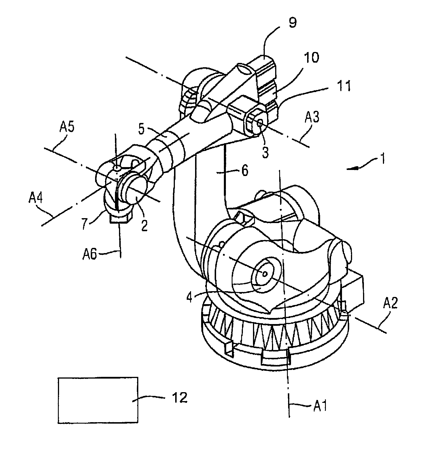
[0037]FIG. 1 shows a robot 1 with kinematics for movements in, for example, six degrees of freedom. The robot 1 has (in a generally known manner) articulations 2 through 4, arms 5, 6, six movement axes A1 through A6 and a flange 7 at which an effector (for example a tool; not shown in detail) can be attached.

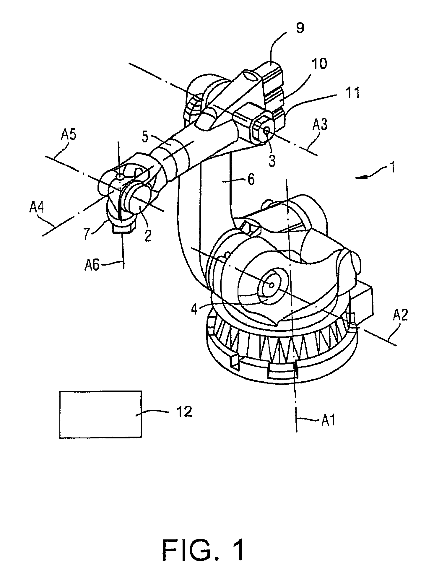
[0038]Each of the movement axes A1 through A6 is moved by an actuator (not shown in detail). The actuators respectively comprise an electrical motor 9-11, 21, for example, as it is generally known to those skilled in the art. FIG. 2 shows the arm 5 that can be pivoted on the axis A3 by means of the motor 21.

[0039]In the case of the present exemplary embodiment, the electrical actuator associated with the axis A3 possesses a gearing 23. A movement of the arm 5 relative to the axis A3 can also be braked with a brake 22. A torque acting on the axis A3 is measured with a torque sensor 24. A torque sensor and a brake can likewise respectively be associated with the remaining axes A1,...


PUM

PropertyMeasurementUnit
torqueaaaaaaaaaa
speedaaaaaaaaaa
actuation torqueaaaaaaaaaa

Abstract

In a method to test a brake of a robot that has a number of axes, an actuator associated with one of the axes, a brake associated with this axis that is set up to at least reduce a movement of this axis, and a torque sensor associated with this axis, which determines the torque acting on this axis. The brake is activated, the torque acting on the axis is determined by the torque sensor given an activated brake, and the functional capability of the brake is assessed in a processor based on an evaluation of the torque determined by the torque sensor.

Description

BACKGROUND OF THE INVENTION[0001]1. Field of the Invention[0002]The invention concerns a method to test a brake of a robot.[0003]2. Description of the Prior Art[0004]Robots are manipulation machines that are equipped for independent handling of objects with appropriate tools and can be programmed in multiple movement axes, in particular with regard to orientation, position and workflow. Robots essentially possess a robot arm with multiple axes and arms that are moved by actuators. The actuators are, for example, electrical actuators.[0005]In order to stop the movement of the robot, these normally possess brakes. For early detection of a potential failure of the brake of an electromotor of a robot (caused by wear or fouling, for example), EP 1 215 475 B1 discloses to engage the brake of an electromotor for a short time in a rotation speed-regulated operation and to measure at least the motor current of the electromotor during this time period in order to determine the braking torque ...

Claims


Application Information

Patent Timeline
Patent Type & Authority Patents(United States)
IPC IPC(8): G01L5/28
CPCB25J13/085B25J19/0004G01L5/288B25J19/0095G01M13/02G01L5/28B25J19/00G01M99/00
Inventor ORTMAIER, TOBIASUEBERLE, MARC-WALTER
Owner KUKA LAB GMBH
Why Eureka
Try Eureka