Method and apparatus for determining formation pararmeters using a seismic tool array

a technology of seismic tool array and method, which is applied in the direction of instruments, survey, borehole/well accessories, etc., can solve the problems of clock drift, inability to acquire seismic data, and high cost of additional downtime or non-drilling tim

Active Publication Date: 2011-12-06
SCHLUMBERGER TECH CORP
View PDF10 Cites 11 Cited by
  • Summary
  • Abstract
  • Description
  • Claims
  • Application Information

AI Technical Summary

Problems solved by technology

Since seismic data cannot be acquired while drilling because of high noise, acquisition is performed each time drilling ceases.
Such an operation is not preferred because of rig time is expensive and additional downtime or non-drilling time is costly.
A further limitation of the current Borehole Seismic While Drilling tools is the clock drift that occurs when the tool has been drilling for an extended period of time.
This drift then causes inaccuracies in the interpretation of the received data.
Since the drill pipe has to be pulled up, or possibly some joints of the drill pipe have to be removed at the surface to lift the tool to the depth where the previous checkshot was performed, the clock calibration requires rig downtime which, again, is expensive.

Method used


Image

  • Method and apparatus for determining formation pararmeters using a seismic tool array
  • Method and apparatus for determining formation pararmeters using a seismic tool array
  • Method and apparatus for determining formation pararmeters using a seismic tool array

Examples


Embodiment Construction

[0035]So that the above recited features and advantages of the present disclosure can be understood in detail, a more particular description of the invention, briefly summarized above, may be had by reference to the embodiments thereof that are illustrated in the accompanied drawings. It is to be noted, however, that the drawings illustrate only typical embodiments of this invention and are therefore not to be considered limiting of its scope, for the invention may admit to other equally effective embodiments.

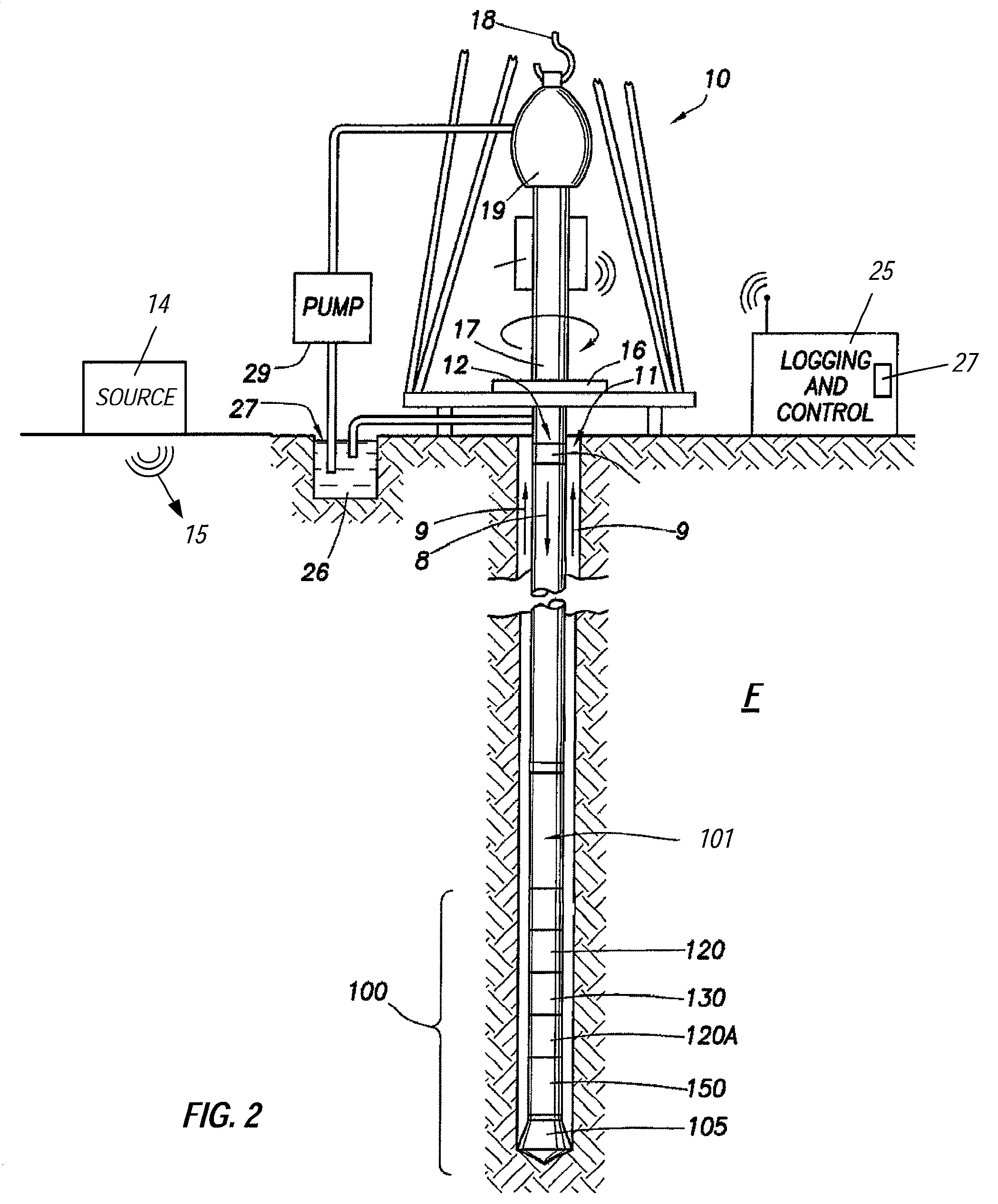
[0036]FIG. 2 illustrates a wellsite system in which the present invention can be employed. The wellsite can be onshore or offshore. In this exemplary system, a borehole 11 is formed in subsurface formations by rotary drilling in a manner that is well known. Embodiments of the invention can also use directional drilling or drilling with a mud motor, as will be described hereinafter.

[0037]A drill string 12, that includes a plurality of drill pipes 101, is suspended within the bor...


PUM


Abstract

A method and apparatus for determining formation parameters including a seismic array for receiving seismic waves at plurality of depth simultaneously, thereby enabling a determination of a formation velocity by using a difference in the seismic waves received by the various portions of the array.

Description

CROSS REFERENCE TO RELATED APPLICATIONS[0001]This application is a non-provisional application of U.S. Provisional Patent Application 60 / 991,216, filed 29 Nov. 2007, the content of which is incorporated herein by reference for all purposes.BACKGROUND OF THE DISCLOSURE[0002]1. Field of the Invention[0003]The present disclosure relates to techniques for acquiring downhole seismic data of a formation, and, more particularly, to techniques using a multi-level seismic tool to acquire seismic data simultaneously at multiple location or depths.[0004]2. Background of the Related Art[0005]Existing Borehole Seismic While Drilling tools contain seismic receivers with a highly accurate downhole clock. The seismic sensors are disposed in a drill collar to record borehole seismic data while drilling ceases, as shown in FIG. 1. The tool digitizes the received seismic signals or waves and puts the data into a circular buffer. In other words, as the tool is drilling seismic data is typically buffere...

Claims


Application Information

Patent Timeline
Patent Type & Authority Patents(United States)
IPC IPC(8): E21B47/00
CPCG01V1/303G01V1/42
Inventor KAMATA, MASAHIRO
Owner SCHLUMBERGER TECH CORP
Why Eureka
Try Eureka