
Spring clip for mounting a sensor on a disk-brake brakeshoe backing plate

a technology of brakeshoe and wear sensor, which is applied in the direction of brake types, friction linings, mechanical apparatus, etc., can solve the problem of clip noise still occurring

Active Publication Date: 2011-12-06
HIRSCHMANN AUSTRIA GMBH
View PDF12 Cites 3 Cited by
  • Summary
  • Abstract
  • Description
  • Claims
  • Application Information

AI Technical Summary

Benefits of technology

[0004]The invention therefore has the object of eliminating the still occurring noise problems that occur under adverse circumstances from relative motion of the brakeshoe wear sensor relative to the brake so that they no longer occur or no longer occur in a disturbing manner.SUMMARY OF THE INVENTION
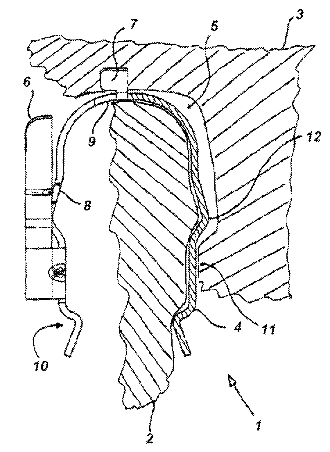
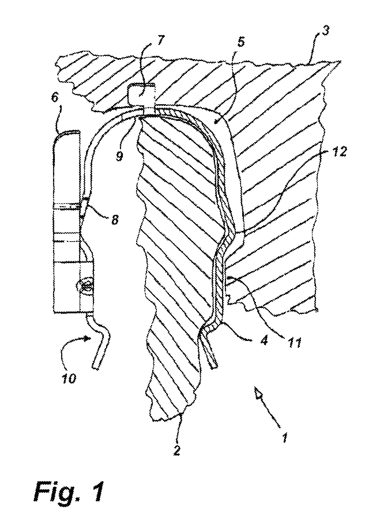
[0005]This object is attained in that a bent tab projects from the spring clip in sections and bears at least partially on the face of the brakeshoe backing plate when the wear sensor is inserted into the seat by the spring clip. This at least partially sectional contacting of the bent tab of the spring clip, which is supported on the other side on the wear sensor, on the face of the brakeshoe backing plate, has the advantage that the brakeshoe backing plate can no longer move parallel or perpendicular to the face of the brakeshoe backing plate preferably in neither direction, which eliminates the disturbing noises caused by the previously known possibility of movement. The at least partial bent tabs on the spring clip can be bent from the one front side of the legs of the spring clip, for example, substantially at a right angle, and it is furthermore also conceivable that such bent tabs project on both front sides of the legs of the spring clip and include their surfaces after its insertion into the seat of the backing plate.
[0006]Thus, the substantially U-shaped spring clip of the invention offers the advantage that it can be easily installed, which is associated with a simple installation of the brakeshoe wear sensor in the seat of the brakeshoe backing plate. Moreover, such a spring clip can be produced rapidly and economically in large numbers from appropriate material, e.g. spring steel, in a simple process, preferably in a stamp bending process, and offers a solution in an especially advantageous manner for the effective elimination of disturbing noises arising from a motion of the wear sensor relative to the brakeshoe backing plate.

Problems solved by technology

As a result of this design of the spring clip noise problems occurring under adverse circumstances are partially but not completely eliminated because it was found in the operation of disk brakes in vehicles that in spite of this known design of the spring clip noise problems still occur.

Method used


Image

  • Spring clip for mounting a sensor on a disk-brake brakeshoe backing plate
  • Spring clip for mounting a sensor on a disk-brake brakeshoe backing plate
  • Spring clip for mounting a sensor on a disk-brake brakeshoe backing plate

Examples


Embodiment Construction

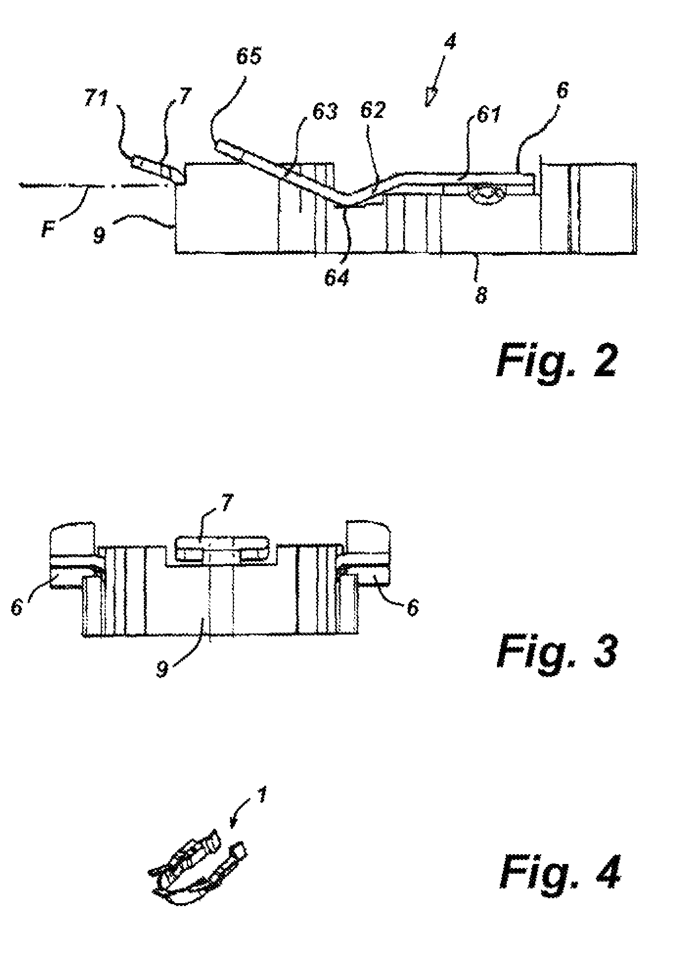
[0013]FIGS. 1 to 4 show, in as much as they show details, a holder 1 for a brakeshoe wear sensor 2 shown here in hatched and in section. The wear sensor 2 is held in a brakeshoe backing plate 3, also shown hatched and in section, by a spring clip 4 that is substantially U-shaped and holds the wear sensor 2 at least in sections in a corresponding recess or seat 5 of the brakeshoe backing plate 3 in such a manner that it cannot be lost, and that parts of legs, in particular the lateral and approximately parallel legs of the spring clip 4, bear on the seat 5 and on the wear sensor 2. Inwardly facing bumps 11 located opposite one another can also be provided inside the seat 5 in the brakeshoe backing plate 3, on which bumps 11 the legs of the spring clip 4 closely rest in sections.

[0014]The spring clip 4 is characterized in accordance with the invention in that at least one bent tab 6 or 7 projects from a portion of at least one of the legs 8, preferably from both legs 8, and from a fro...


PUM


Abstract

A brakeshoe having a backing plate formed with a seat recess opening at a face, is provided with a brakeshoe wear sensor held in place by a U-shaped spring clip. The clip is formed with a pair of legs extending generally parallel to each other and spaced so as to fit around the sensor and a front end extending between the legs and joining same together. The legs and front end fit wholly in the seat recess between the sensor and the backing plate and bear on the sensor and backing plate. A bent-out tab projects transversely from each of the legs and bears outside the recess on the face of the backing plate.

Description

FIELD OF THE INVENTION[0001]The invention relates to a spring-clip holder for a brakeshoe wear sensor in a brakeshoe backing plate that is designed substantially in a U-shape and holds the wear sensor in sections in a complementary seat of the brakeshoe backing plate in such a manner that it cannot be lost in that parts of legs of the spring clip rest on the seat and on the wear sensor in in an assembly where a substantially U-shaped spring clip holds the wear sensor in sections in a corresponding seat of the brakeshoe backing plate in such a manner that it cannot be lost and parts of legs of the spring clip rest on the seat and on the wear sensor.BACKGROUND OF THE INVENTION[0002]Brakeshoe wear sensors mounted on a brakeshoe backing plate, detecting wear of a brakeshoe of a disk brake of a motor vehicle, and generating an output signal are known, for example, from DE 34 25 870, DE 32 30 266, DE 31 32 054, DE 43 40 452, DE 39 04 673, DE 70 47 480, or DE 695 07 820.[0003]A generic hol...

Claims


Application Information

Patent Timeline
IPC IPC(8): F16D66/02
CPCF16D66/024F16D66/027
Inventor WILLE, MANUELJAGER, GUNTER
Owner HIRSCHMANN AUSTRIA GMBH
Learn More