Strain monitoring system and apparatus

a technology of strain monitoring and monitoring system, applied in the field of strain monitoring system and apparatus, can solve the problems of small pads of cartilage that can become damaged, chronic pain and loss of function in the spine, and injury of the back muscles

Active Publication Date: 2011-12-06
SCHENBERGER DEBORAH +1
View PDF24 Cites 58 Cited by
  • Summary
  • Abstract
  • Description
  • Claims
  • Application Information

AI Technical Summary

Benefits of technology

[0022]The present invention comprises a system and apparatus that satisfies the foregoing needs through the use of four main features: strain sensing, integrated microfabricated circuitry, RF signal transmission, and data collection. According to an aspect of the invention, the sensor comprises an inter-digitated capacitor. Another aspect of the invention is the microminiaturization of a strain sensing system. Using the techniques of the present invention, a strain sensing system can be microscopic in size. The resultant miniaturization allows the system to be incorporated or integrated into an implant or other device. Another aspect of the invention is the elimination of the need for an internal battery power supply or external leads connecting the system to an external power supply. This is accomplished through the use of an inductively coupled power supply.
[0025]Accordingly, the present invention generally comprises an implantable inter-digitated capacitor based strain sensor system that can produce a reliable, reproducible signal that will indicate via a radio telemetry signal when strain has changed.
[0026]In one exemplary embodiment, the invention contains a strain sensor that will accurately measure low levels of strain and transmit the data using an RF transmitter and associated antennal. In another embodiment, the implantable portion of the system is inductively powered by an external electromagnetic power source to avoid the complications of implanting batteries within humans. Otherwise, batteries can be mounted subcutaneously and later removed.

Problems solved by technology

Most frequently, inappropriate lifting of objects, pulling or lifting objects from awkward angles, and fatigue lead to injury of the back muscles.
In between the processes, there are small pads of cartilage that can become damaged with a back injury.
Both herniated discs and the processes can cause chronic pain and loss of function in the spine.
Pain results in debilitation and prevents the patient from enjoying ordinary daily activities.
The brace also contributes to stress shielding, meaning the brace is carrying some of the spinal load, resulting in an inferior strength lumbar fusion.
The problem with the foregoing treatment approach, is that fusion occurs much sooner than is predicted by radiographs.
However, the bone that initially grows around the spinal instrumentation is trabecular bone, and although it is strong and dense, it is not radiographically opaque.
Thus, it cannot be seen on an x-ray until it has been infused with minerals, such as calcium.
In addition, the device does not use an internal power source.
Notwithstanding the foregoing approaches to measuring strain, the onset of spinal fusion after lumbar surgery continues to be difficult to determine, and patients are frequently fitted with a spinal brace for three to six months after surgery even though the implant provides internal fixation in a much shorter period of time.

Method used


Image

  • Strain monitoring system and apparatus
  • Strain monitoring system and apparatus
  • Strain monitoring system and apparatus

Examples


Embodiment Construction

[0059]Referring more specifically to the drawings, for illustrative purposes the present invention is embodied in the system, apparatus, devices and methods generally shown in FIG. 1 through FIG. 22.

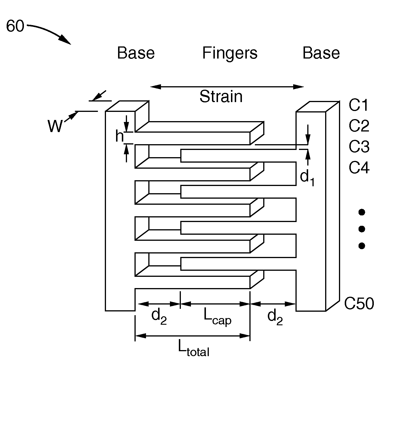
[0060]In general terms, the present invention is embodied in a system that employs capacitive inter-digitated strain sensing and RF signal transmission using integrated microfabricated circuitry. The present invention generally comprises an implantable capacitive strain sensor that can produce a reliable, reproducible signal that will indicate via a radio telemetry signal when strain has changed. An embodiment of the system includes an internal power supply subsystem that is configured for inductive coupling to an external power source so that batteries are not required. A further embodiment of the system includes a receiver subsystem to which sensed data is transmitted and collected. Additional embodiments include variations of the foregoing.

[0061]The present invention will be described...


PUM


Abstract

A system for monitoring strain as an indicator of biological conditions, such as spinal fusion, glucose levels, spinal loading, and heart rate. The system includes an inter-digitated capacitor sensor, and RF transmitter, and an associated antenna, all of which are microminiature or microscopic in size and can be implanted in a biological host such as a human or animal. An inductively coupled power supply is also employed to avoid the need for implantation of chemical batteries. Power is provided to the sensor and transmitter, and data is transmitted from the sensor, when an external receiving device, such as a handheld RF ID type receiver, is placed proximate the location of the implanted sensor, transmitter and inductively coupled power supply. The implanted sensor, transmitter and inductively coupled power supply can be left in place permanently or removed when desired.

Description

CROSS-REFERENCE TO RELATED APPLICATIONS[0001]This application claims priority from, and is a 35 U.S.C. §111 (a) continuation of, PCT international application serial number PCT / US2005 / 024340, filed on Jul. 8, 2005, incorporated herein by reference in its entirety, which claims priority from U.S. provisional application Ser. No. 60 / 586,593 filed on Jul. 8, 2004, incorporated herein by reference in its entirety.STATEMENT REGARDING FEDERALLY SPONSORED RESEARCH OR DEVELOPMENT[0002]Not ApplicableINCORPORATION-BY-REFERENCE OF MATERIAL SUBMITTED ON A COMPACT DISC[0003]Not ApplicableNOTICE OF MATERIAL SUBJECT TO COPYRIGHT PROTECTION[0004]A portion of the material in this patent document is subject to copyright protection under the copyright laws of the United States and of other countries. The owner of the copyright rights has no objection to the facsimile reproduction by anyone of the patent document or the patent disclosure, as it appears in the United States Patent and Trademark Office p...

Claims


Application Information

Patent Timeline
Patent Type & Authority Patents(United States)
IPC IPC(8): A61B5/103A61B5/117
CPCA61B5/0031A61B5/1036A61B5/14532A61B5/14546A61B5/4566A61B5/6846A61B5/1126A61B19/46A61B2019/448A61B2019/464A61B2560/0219A61B2562/0261A61B2562/028A61F2/4455A61F2/4657A61F2002/30668A61F2250/0001A61B2090/064A61B90/98A61B90/06A61B5/0205A61B5/024A61B5/076A61B5/103A61B5/686
Inventor GUPTA, MUNISHSCHENBERGER, DEBORAHLEE, EUNICERAMAHI, AMJAD
Owner SCHENBERGER DEBORAH
Why Eureka
Try Eureka