Contactless charging system for an artificial organ, a storage device and a feeding device for use with this system

a charging system and artificial organ technology, applied in the field of contactless charging system for artificial organs, storage devices and feeding devices for use with this system, can solve the problems of heavy burden on the body, the battery cannot be charged from outside the body while the battery remains, etc., to avoid complication in device construction, facilitate correction, and large capacity

Inactive Publication Date: 2011-08-16
LIMITED COMPANY TM
View PDF17 Cites 58 Cited by
  • Summary
  • Abstract
  • Description
  • Claims
  • Application Information

AI Technical Summary

Benefits of technology

[0010]The charge status of the storage means in the storage device is detected in the storage device inside the body and transmitted outside the body, and is received and reported by the feeding device outside the body. Thus, the charge status of the storage means may be checked during charging. As a result, a shortage of charging is avoided and the storage means may be charged reliably.
[0013]That is, the amount of coil displacement between the power receiving coil means and power transmitting coil means is detected by the amount of coil displacement detecting means, and is reported by the amount of coil displacement informing means outside the body. It is thus possible to know the extent of the displacement between the power receiving coil means and power transmitting coil means. Since both coils can be set to proper positions by resetting both the coil means according to the extent of the displacement, charging of the storage device may be carried out efficiently.
[0015]That is, the amount of coil displacement detecting means is disposed in the storage device, and the amount of coil displacement detected is transmitted outside the body along with the charge status by using the charge status transmitting means. It is thus possible to avoid complication of the device construction. By displaying the amount of coil displacement on the display means, a positional adjustment of the power receiving coil means and power transmitting coil means may be carried out easily for correction of the amount of coil displacement.
[0019]With the above construction, the direction of coil displacement between the power receiving coil means and power transmitting coil means is detected by the direction of coil displacement detecting means, and is reported by the direction of coil displacement informing means outside the body. It is thus possible to know the direction of the displacement between the power receiving coil means and power transmitting coil means. Therefore, the displacement between the power receiving coil means and power transmitting coil means may be corrected easily.
[0021]That is, the direction of coil displacement detecting means is disposed in the storage device, and the direction of coil displacement detected is transmitted outside the body along with the charge status by using the charge status transmitting means. It is thus possible to avoid complication of the device construction. By displaying the direction of coil displacement on the display means, a positional adjustment of the power receiving coil means and power transmitting coil means may be carried out easily for correction of the direction of coil displacement.
[0022]In the contactless charging system for an artificial organ according to this invention, it is preferable that the storage means of the storage device is a rechargeable battery or an electric double layer capacitor. Where, for example, an electric double layer capacitor is used, which is small but has a large capacity, it is compact and has a sufficient storage function, has a long life with little deterioration or the like by repeated charging, and moreover is low in heat generation. Thus, the storage means in the form of an electric double layer capacitor is better than other, rechargeable batteries and the like.

Problems solved by technology

However, in the case of the above conventional example, there is a problem that the battery cannot be charged from outside the body while the battery remains embedded in the body.
However, the battery changing operation for incising the body imposes a heavy burden especially on a person having trouble with the heart.

Method used


Image

  • Contactless charging system for an artificial organ, a storage device and a feeding device for use with this system
  • Contactless charging system for an artificial organ, a storage device and a feeding device for use with this system
  • Contactless charging system for an artificial organ, a storage device and a feeding device for use with this system

Examples


Embodiment Construction

[0039]Modes for solving the problem of the prior art include the following.

[0040]An embodiment of this invention will be described hereinafter with reference to the drawings.

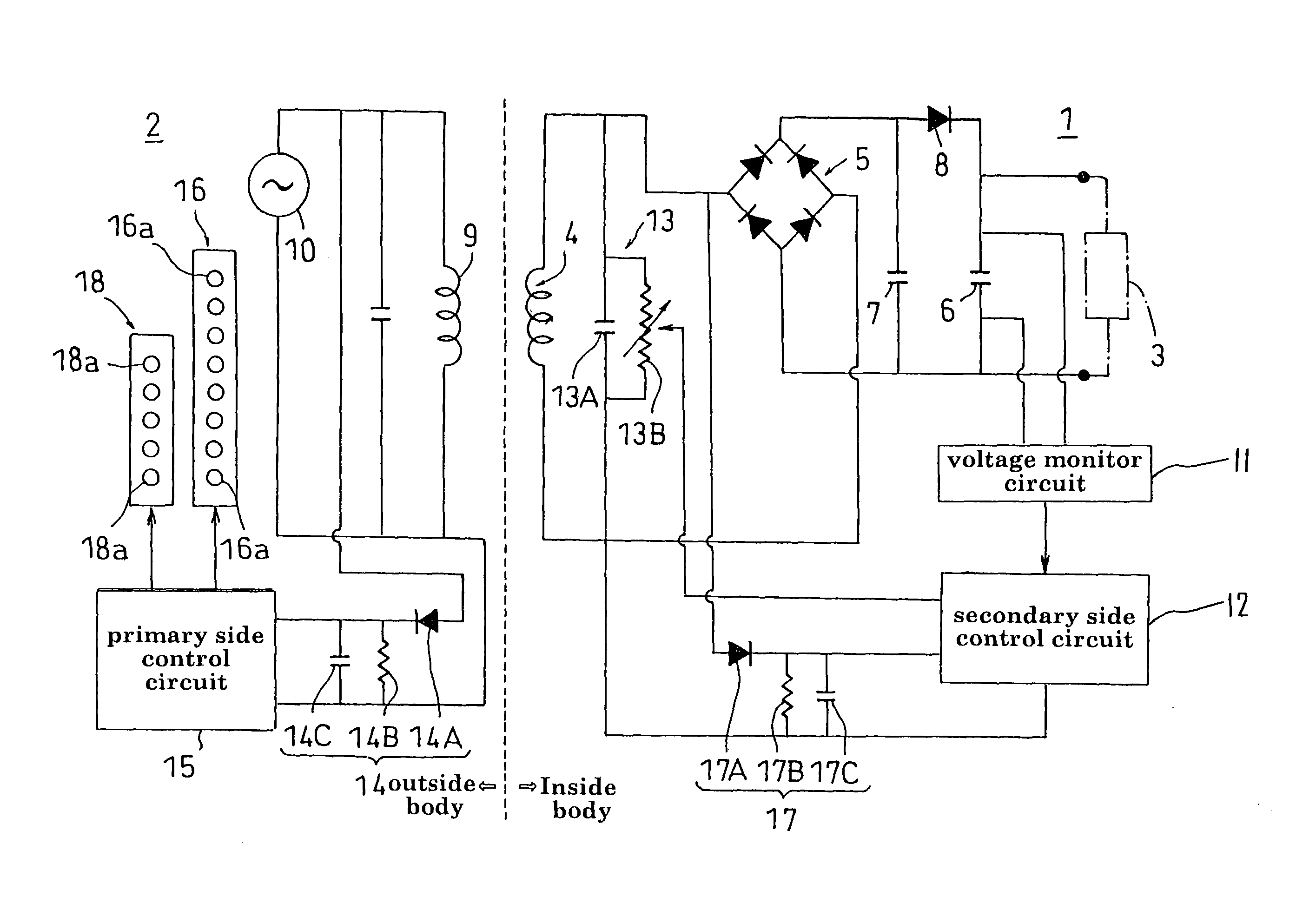
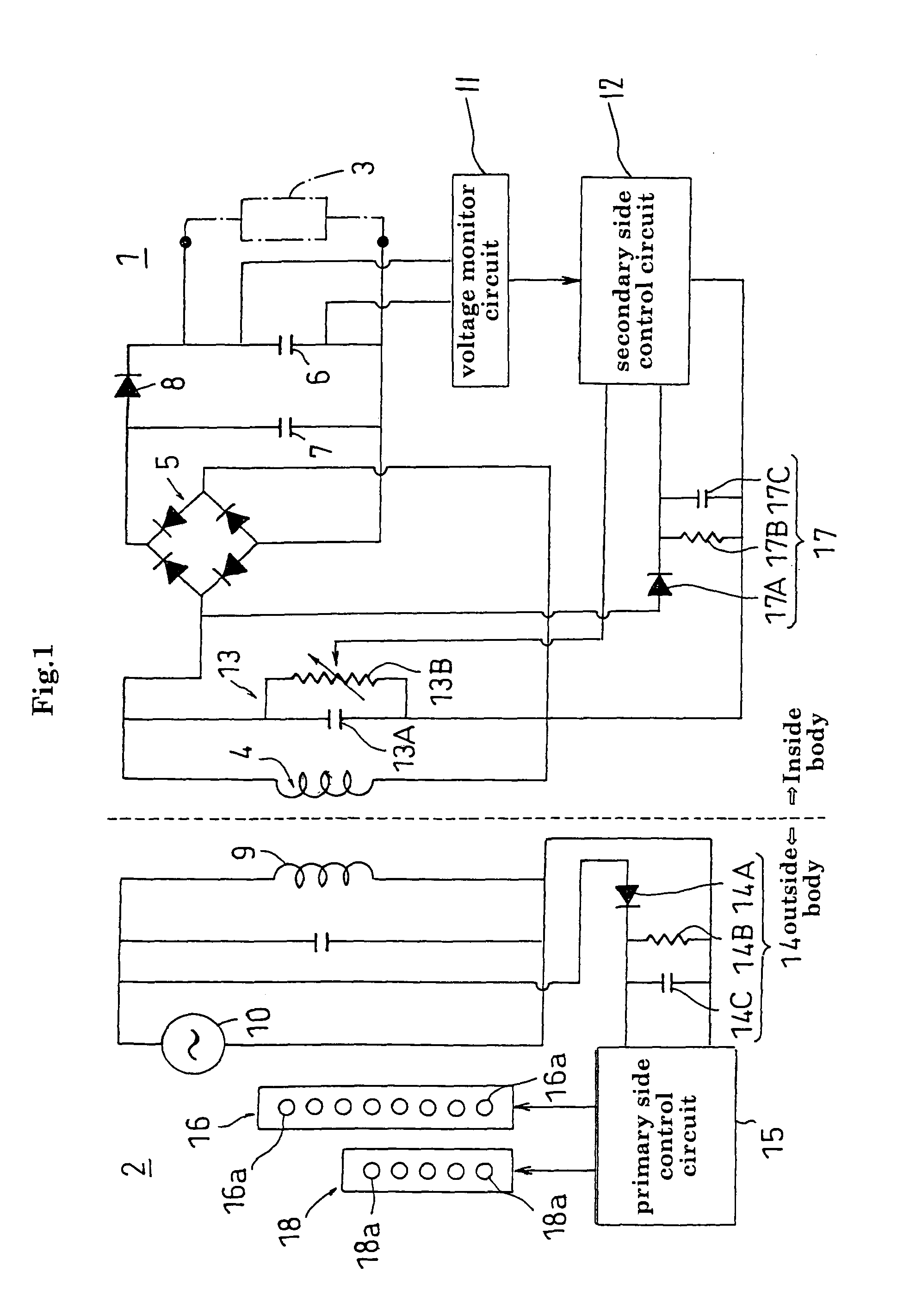
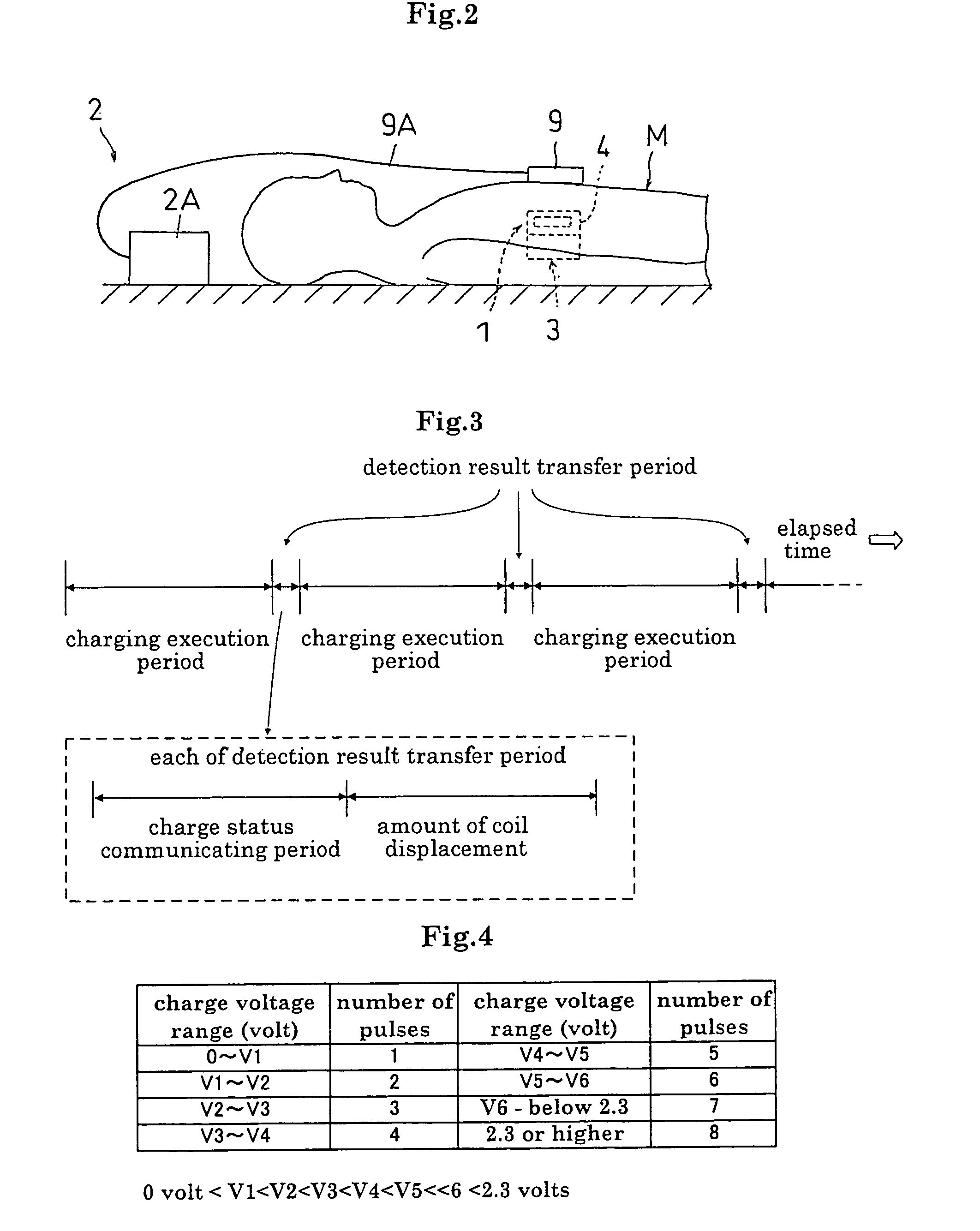
[0041]An embodiment of each of a contactless charging system for an artificial organ, and a storage device and a feeding device for use with this system, according to this invention, will be described hereinafter. FIG. 1 is a block diagram showing an entire construction of the charging system according to the embodiment. FIG. 2 is a schematic view showing a situation in time of charging by the charging system in the embodiment.

[0042]The charging system in the embodiment, as shown in FIGS. 1 and 2, includes a storage device 1 wholly embedded, as molded in a silicone resin or the like together with a cardiac pacemaker 3 acting as an artificial organ, for example, in the body of a user M of the pacemaker 3, and a feeding device formed separately from this storage device 1 and disposed as a whole outside the body of...


PUM

PropertyMeasurementUnit
frequencyaaaaaaaaaa
diameteraaaaaaaaaa
charge voltageaaaaaaaaaa

Abstract

According to a charging system of this invention, an alternating current required for charging of an electric double layer capacitor of a storage device in the body may be transmitted from a feeding device outside the body through power receiving and power transmitting coils. The electric double layer capacitor may be charged in a contactless mode, without incising the body of the artificial organ user, while the storage device remains embedded in the body. The electric double layer capacitor may be charged reliably by avoiding a shortage of charging since the charge status of the electric double layer capacitor of the storage device is known during a charging operation.

Description

TECHNICAL FIELD[0001]This invention relates to a charging system for an artificial organ having a storage device embedded in the body along with the artificial organ to act as an artificial organ driving power source, and a feeding device for feeding power to the storage device, and particularly to a technique for enabling a reliable charging in a contactless mode of the storage device remaining embedded in the body.BACKGROUND ART[0002]Conventionally, a cardiac pacemaker (hereinafter referred to simply as “pacemaker” where appropriate) exists as one of the artificial organs. The pacemaker is embedded in the body with a battery acting as driving power source. The pacemaker embedded in the body, while receiving a supply of driving electric power from the battery, causes the heart to beat regularly by directly applying an electrical pulse to and stimulating the heart. A nickel cadmium cell, lithium cell or the like is used for the battery acting as the driving power source of the cardi...

Claims


Application Information

Patent Timeline
Patent Type & Authority Patents(United States)
IPC IPC(8): A61N1/378H01M10/44H01M10/48H02J7/00
CPCA61N1/3787H02J7/025H02J7/00034H02J50/90H02J50/12H02J2310/23
Inventor TAKEDA, HARUMIHIRAKAWA, TAKAHIRO
Owner LIMITED COMPANY TM
Why Eureka
Try Eureka