Power converter apparatus

a technology of power converter and power converter, which is applied in the direction of dc-ac conversion without reversal, power conversion system, electrical apparatus, etc., can solve the problems of difficult to charge up the dc capacitor in an arbitrary cell alone, and achieve the effect of preventing excessive voltage application and excessive charge to the dc capacitor

Active Publication Date: 2011-01-27
HITACHI LTD
View PDF5 Cites 67 Cited by
  • Summary
  • Abstract
  • Description
  • Claims
  • Application Information

AI Technical Summary

Benefits of technology

[0017]The power converter apparatus includes a unit that turns on a lower cascade arm IGBT of the bidirectional chopper circuit of the unit cell except for the unit cell selected at the time of initially charging up the DC capacitor to turn on the lower cascade arm IGBT in the unit cell except for the unit cell selected, and bypass a charge current to the DC capacitor by the lower cascade arm IGBT, so that the charge-up to the DC capacitor in the unit cell, which is not selected, can be prevented.
[0018]The power converter apparatus sets a maximum value of the voltage in the variable voltage source to a rated voltage of the DC capacitor in the unit cell, while adjusting the voltage of the variable voltage source connected with the DC link, to perform the initial charge, so that an excessive voltage application and excessive charge to the DC capacitor can be prevented.

Problems solved by technology

Therefore, it is difficult to charge up the DC capacitor in an arbitrary cell alone.

Method used


Image

  • Power converter apparatus
  • Power converter apparatus
  • Power converter apparatus

Examples


first embodiment

[0025]A first embodiment of the invention will be described below.

[0026]In the first embodiment, a modular multilevel converter (MMC) will be described as an example in the invention.

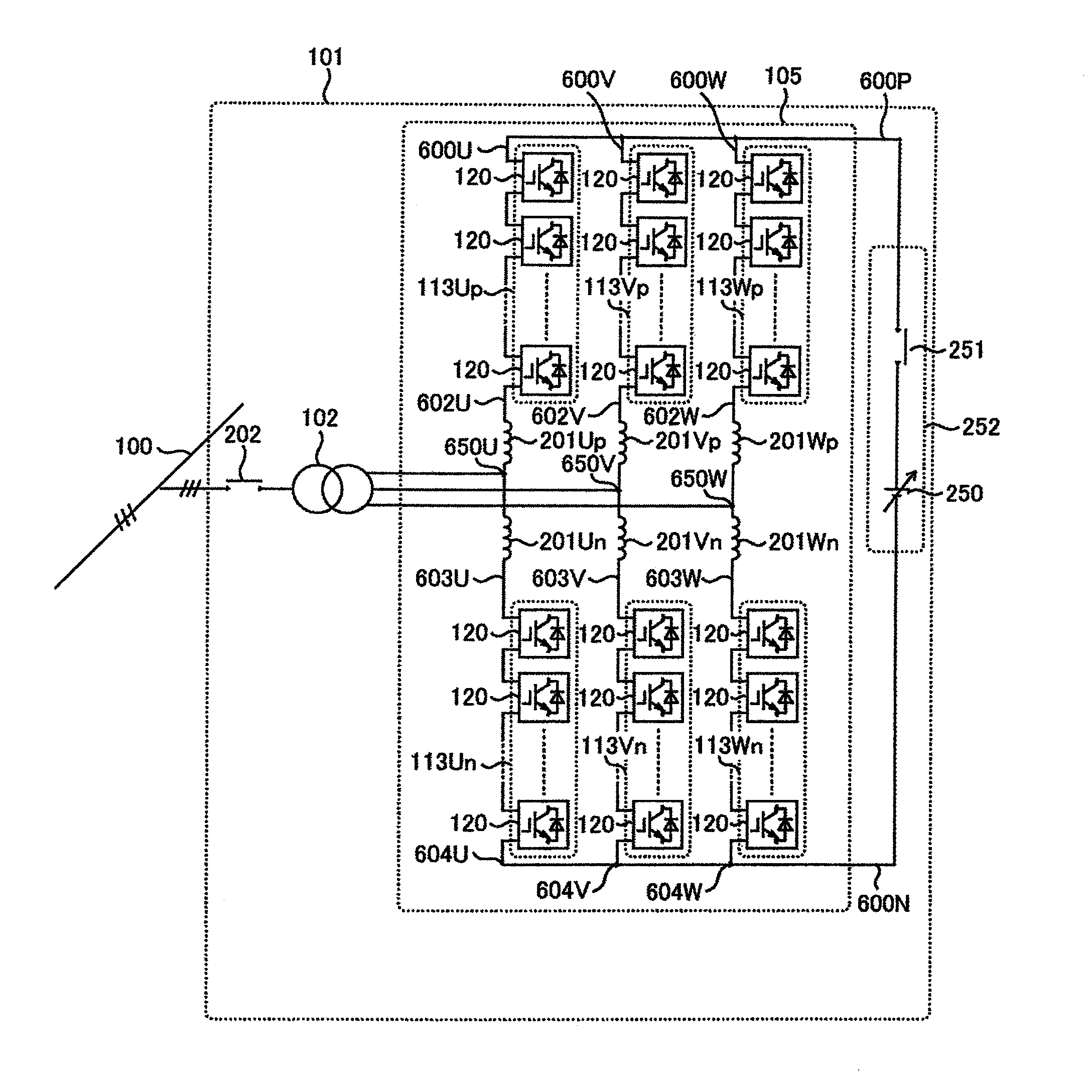
[0027]FIG. 1 is a circuit diagram in the first embodiment of the invention. A configuration of a power converter apparatus 101 in the invention will be described first with reference to FIG. 1.

[0028]The power converter apparatus 101 is configured by six pieces of cascade arms 113Up, 113Vp, 113Wp, 113Un, 113Vn, 113Wn, arm reactors 201Up, 201Vp, 201Wp, 201Un, 201Vn, 201Wn and a linked transformer 102, a breaker 202, and a cell initial charge-up circuit 252.

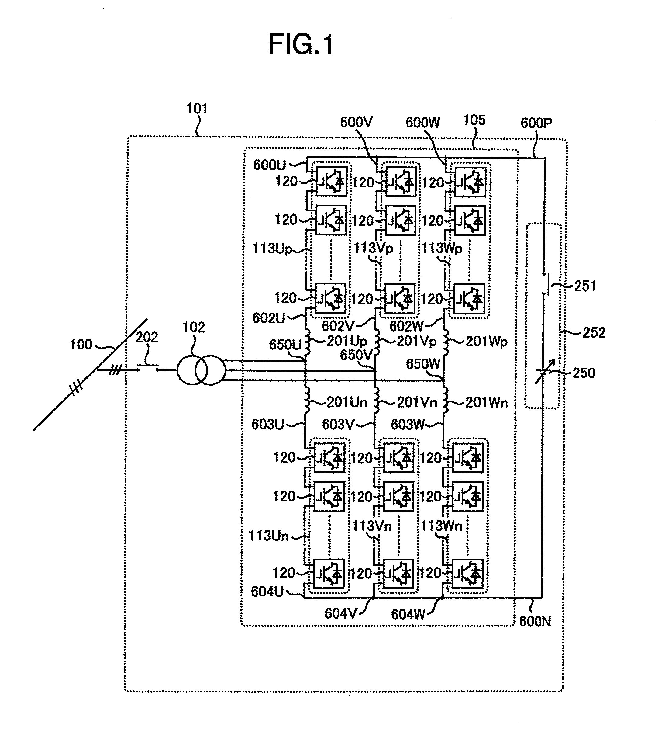
[0029]Unit cells 120 are configured by a bidirectional chopper circuit 120C shown in FIG. 2. The bidirectional chopper circuit 120C provides an IGBT leg 411 configured by an IGBT parallel module 402P and an IGBT parallel module 402N as semiconductor devices, and a DC capacitor 406 connected with the IGBT leg 411.

[0030]The IGBT parallel modules 402P, 402...

second embodiment

[0049]The unit cell 120 in the power converter apparatus 101 of the first embodiment is configured by the bidirectional chopper circuit 120C. In contrast, a second embodiment has an aspect that the unit cell 120 is configured by a full bridge circuit 120F.

[0050]First, a configuration of the power converter apparatus 101 in the second embodiment will be described below. As described above, the second embodiment is only different from the first embodiment in the unit cell 120, therefore, the configuration of unit cell 120 will only be described below.

[0051]FIG. 3 shows a configuration of the full bridge circuit 120F configuring the unit cell 120 in the second embodiment. The full bridge circuit 120F or 120 has two-parallel IGBT legs 411L, 411R, both of which are connected in parallel with the DC capacitor 406. The IGBT legs 411L, 411R have respectively the IGBT parallel modules 402P, 402N, both of which are connected in series, similarly to the first embodiment. An input / output termin...

third embodiment

[0057]A third embodiment has an aspect to have a function that initially charges up the DC capacitor from the three-phase power system 100. FIG. 4 shows a configuration of the power converter apparatus 101 in the third embodiment. The power converter apparatus 101 in this embodiment has a variable voltage transformer 102C in place of the initial charge-up circuit 252 shown in FIG. 1 of the first embodiment. Other elements in FIG. 4 are the same as shown in FIG. 1, therefore, description for these will be omitted.

[0058]An operation of the unit cell 120 is basically the same as that of the first and second embodiments. However, when the DC capacitor 406 in an arbitrary unit cell 120 is charged up initially in the third embodiment, the contactor 202 is closed to initially charge up the DC capacitor 406 in the unit cell 120 while adjusting an output voltage of the variable voltage transformer 120C. In contrast, in the first and second embodiments, the contactor 251 is closed under a con...


PUM


Abstract

A power converter apparatus having a configuration of a plurality of unit cells, including a DC capacitor and semiconductor devices, connected in cascade, includes a variable voltage source that is connected with a DC link, and a unit having a function that initially charges up the DC capacitor in the unit cell alone selected at a time of an initial charge.

Description

BACKGROUND OF THE INVENTION[0001]The present invention relates to a power converter apparatus, and in particular to a power converter apparatus linked to an AC power system via a transformer.[0002]A document written by Makoto Hagiwara and Hirofumi Akagi and entitled “PWM Control and Experiment of Modular Multilevel Converters (MMC)” Journal of The Institute of Electrical Engineers of Japan, vol. 128, No. 7, 2008, pp. 957-965, has proposed a modular multilevel converter (MMC) by using switching devices (Insulated-Gate Bipolar Transistor, IGBT etc.) to be able to control on and off, as a system of a power converter apparatus capable of outputting a high voltage exceeded over a withstand voltage of the switching device.[0003]The MMC is a converter using a bidirectional chopper circuit or full bridge circuit, as a unit cell, connected to a DC capacitor, and input and output terminals of that are connected in cascade. The MMC has an aspect that the phase of PWM control carrier wave of th...

Claims


Application Information

Patent Timeline
Patent Type & Authority Applications(United States)
IPC IPC(8): H02M7/515
CPCH02M1/088H02M1/36H02M2007/4835H02M7/483H02M7/4835
Inventor KATOH, SHUJIINOUE, SHIGENORI
Owner HITACHI LTD
Why Eureka
Try Eureka