Optical system

a technology of optical system and optical lens, applied in the field of optical system, can solve problems such as image quality degradation, and achieve the effects of reducing size, high resolution power, and well corrected aberrations

Active Publication Date: 2011-12-06
OLYMPUS CORP
View PDF11 Cites 58 Cited by
  • Summary
  • Abstract
  • Description
  • Claims
  • Application Information

AI Technical Summary

Benefits of technology

[0008]Such being the case, a main object of the invention is to provide an optical system of small-format size, reduced flare light and high resolving power for taking an image having a full 360°-direction (full-panoramic) angle of view or projecting an image at a full 360°-direction (full-panoramic) angle of view.
[0026]With the invention as recited above, it is possible to obtain an optical system that is adapted to obtain an image having a full 360°-direction (full-panoramic) angle of view or projecting an image at a full 360°-angle of view, and that is not affected by flare light and reduced in size, and has well corrected aberrations and high resolving power.

Problems solved by technology

A problem with either of patent publications 1 and 2 is, however, that when full-panoramic images are picked up with the optical system directing to the zenith, much harmful flare light coming from the zenithal direction causes image quality to go worse, because the effective diameter of the first transmitting surface grows large as a consequence of an entrance pupil within a section including a center axis being located the center axis.

Method used


Image

  • Optical system
  • Optical system
  • Optical system

Examples


example 1

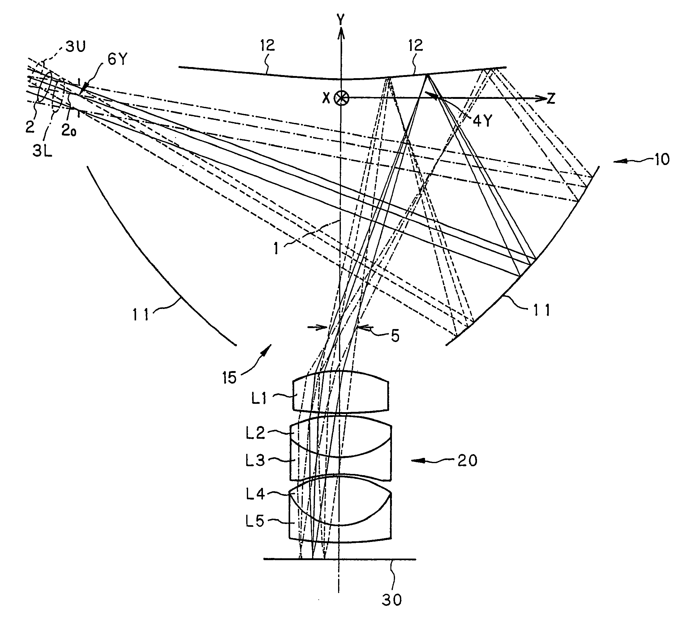
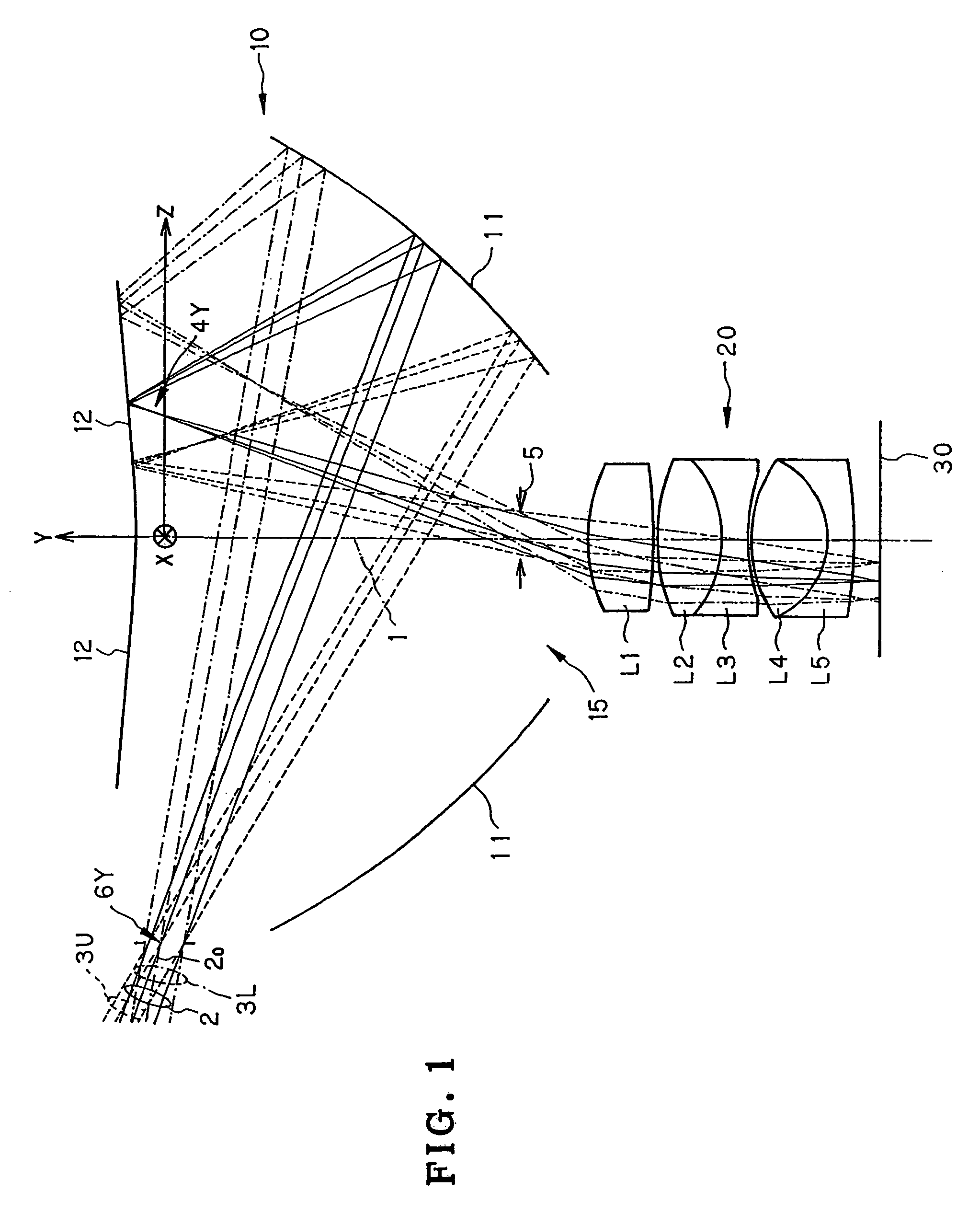
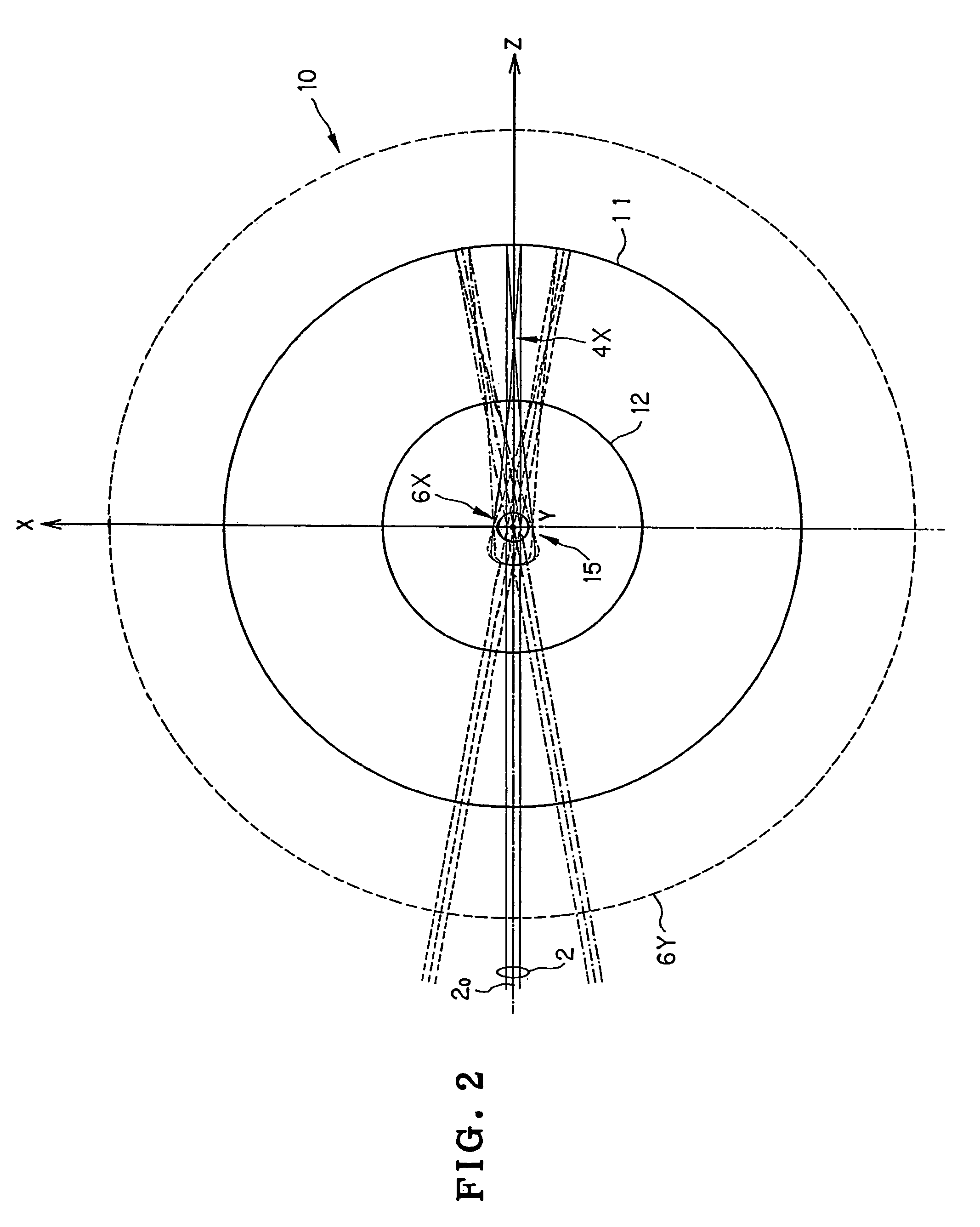
[0098]FIG. 1 is a sectional view of the optical system of Example 1, as taken along a center axis 1 (axis of rotational symmetry), and FIG. 2 is a plan view of an optical path through that optical system. Note here that FIG. 2 shows an optical path coming from the azimuth direction of 0° plus an optical path coming from an azimuth direction of ±10°.

[0099]The optical system of this example is made up of a front unit 10 rotationally symmetric about the center axis 1, a rear unit 20 rotationally symmetric about the center axis 1, and an aperture 5 located between the front unit 10 and the rear unit 20 coaxially with the center axis 1. A light beam 2 coming from a far away object passes through the front unit 10 and the rear unit 20 in order, forming an image at a position of an image plane 30 that is vertical to and off the center axis 1. When the center axis is set vertically, an annular image which has typically a full-360° (full-panoramic) angle of view, and whose zenithal direction...

example 2

[0114]FIG. 4 is a sectional view of the optical system of Example 2, as taken along a center axis 1 (the axis of rotational symmetry), and FIG. 5 is a plan view of an optical path through that optical system. Note here that FIG. 5 shows an optical path incident from the azimuth angle direction of 0° plus an optical path incident from an azimuth angle direction of ±10°.

[0115]The optical system of this example, wherein a resin or other transparent medium 16 having a refractive index of greater than 1 is filled up between a first 11 and a second reflecting surface 12 in a front unit 10, is made up of the front unit 10 rotationally symmetric about the center axis 1, a rear unit 20 rotationally symmetric about the center axis 1, and an aperture 5 located between the front 10 and the rear unit 20 coaxially with the center axis 1. A light beam 2 coming from a far away object passes through the front unit 10 and the rear unit 20 in order, forming an image at a position of an image plane 30 ...

example 3

[0131]FIG. 7 is a sectional view of the relay optical system according to Example 3, as taken along a center axis 1, and FIG. 8 is a sectional view of the relay optical system of this example connected to the image plane 30 side of the optical system according to Example 2.

[0132]This example is directed to a relay optical system 50 for relaying to a second image plane 40 an annular image formed at the image plane 30 of the optical systems according to Examples 1 and 2 of the invention. As noted above, the relay optical system 50 here connected to the image plane 30 side of the optical system according to Example 2 is shown in section in FIG. 8. The relay optical system 50 here is made up of 8 lenses in a seven-group form: in order from the image plane 30 side, a positive meniscus lens L1 concave on its object side, a double-concave negative lens L2, a positive meniscus lens L3 concave on its object side, a double-convex positive lens L4, a double-convex positive lens L5, a cemented ...


PUM


Abstract

An optical system is adapted to form an image having a full 360° angle of view on an image plane. The optical system includes a front unit having at least two reflecting surfaces, each rotationally symmetric about a center axis, and a rear unit that is rotationally symmetric about the center axis and has positive power. The first reflecting surface is located opposite to an entrance pupil, and the second reflecting surface is located on the same side as the first reflecting surface. The entrance pupil in a section including the center axis is located between the outer periphery of the first reflecting surface and the outer periphery of the second reflecting surface. A light beam coming from afar passes through the front unit and the rear unit in order, forming an image at a position of an image plane off the center axis.

Description

ART FIELD[0001]The present invention relates generally to an optical system, and more specifically to an optical system that is of small-format size and high resolving power, and that is well suited for use on all sky cameras, all sky projectors, etc., designed to form on an image plane an image having a full 360°-direction angle of view or project an image located on an image plane at a full 360°-direction angle of view.BACKGROUND OF THE INVENTION[0002]Among prior optical systems using a reflection optical system to obtain full 360°-direction (full-panoramic) images, there is one made up of a front unit comprising a transparent medium that is rotationally symmetric about a center axis and includes two internal reflecting surfaces and two transmitting surfaces and a rear unit that is rotationally symmetric about the center axis and has positive power, as set forth in patent publications 1 and 2.[0003]Patent Publication 1[0004]U.S. Pat. No. 4,566,763[0005]Patent Publication 2[0006]U....

Claims


Application Information

Patent Timeline
Patent Type & Authority Patents(United States)
IPC IPC(8): G02B13/06G02B17/00
CPCG02B13/06G02B17/0804G03B15/00G03B37/00
Inventor TOGINO, TAKAYOSHINAKAMURA, SHIN
Owner OLYMPUS CORP
Why Eureka
Try Eureka