Method for displaying face detection frame, method for displaying character information, and image-taking device
a face detection and character information technology, applied in the field of face detection frames, can solve the problems of user difficulty in determining composition, misalignment between face detection frames and live previews, and user inability to quickly recognize live previews
- Summary
- Abstract
- Description
- Claims
- Application Information
AI Technical Summary
Benefits of technology
Problems solved by technology
Method used
Image
Examples
first embodiment
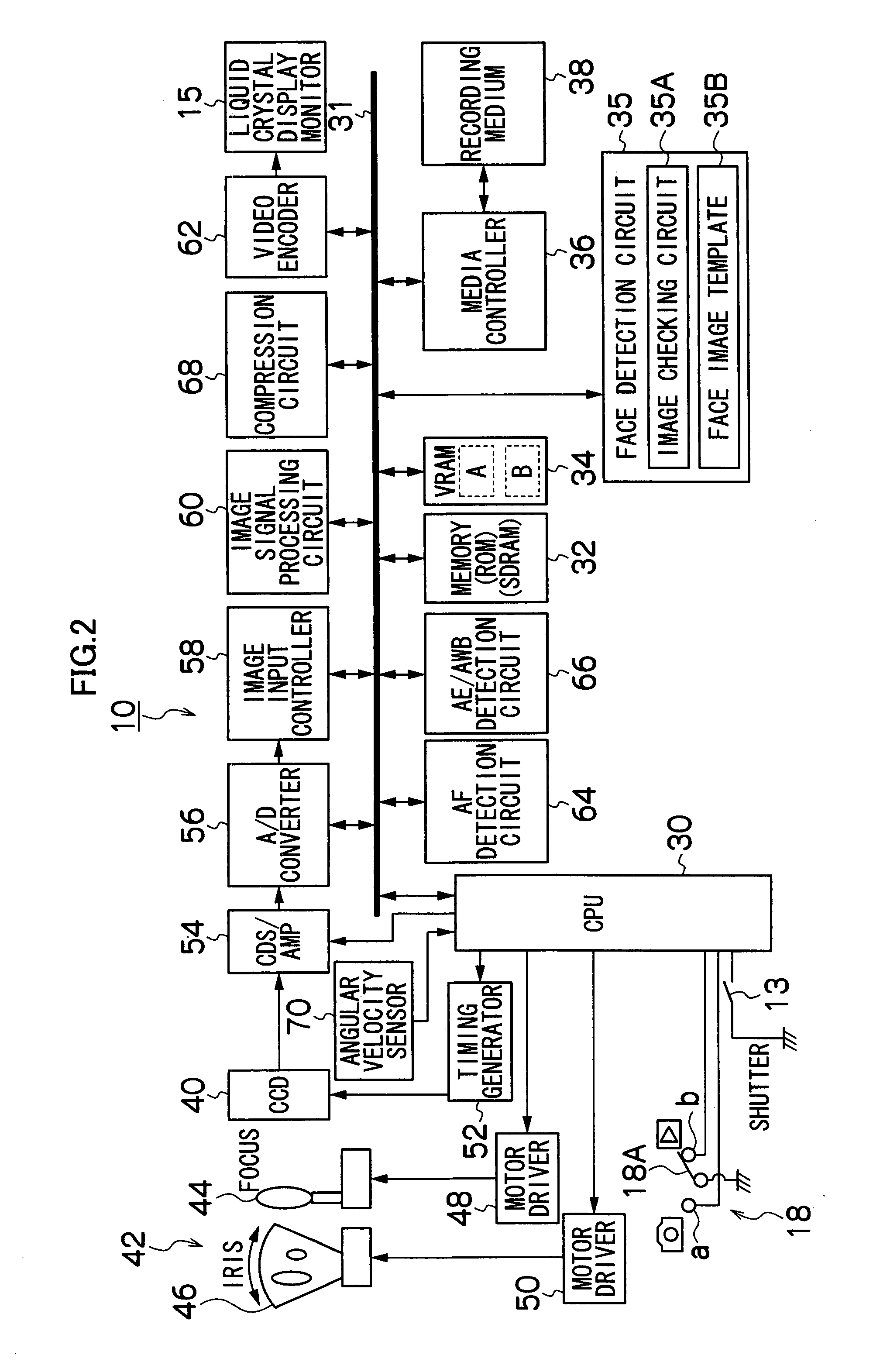
[0065]FIG. 2 is a block diagram illustrating an exemplary internal structure of a first embodiment of the digital camera 10 shown in FIG. 1.
[0066]The overall operation of the digital camera 10 is governed by a central processing unit (CPU) 30. The CPU 30 acts as a control device which controls this camera system according to a predetermined program, and also acts as a computing device which performs various types of operations such as automatic exposure (AE) operations, automatic focus (AF) operations, or white balance (WB) adjustment operations.
[0067]A memory 32, being connected with the CPU 30 via a bus 31, includes a ROM which stores programs executed by the CPU 30 and various types of data needed for controls, and an SDRAM which is used as a deployment area for the programs and a working area for computation by the CPU 30 as well as a temporary storage area for image data. A VRAM 34 is a temporary memory exclusively used for image data and includes areas A and B which image data...
second embodiment
[0116]FIG. 6 is a block diagram illustrating an exemplary internal structure of a second embodiment of the image-taking device (digital camera 10-2) according to the present invention. Note that the same reference numerals are used to refer to the elements in common with the digital camera 10 in FIG. 2 and the detailed description thereof will be omitted.
[0117]The digital camera 10-2 of the second embodiment shown in FIG. 6 is different from the digital camera 10 of the first embodiment shown in FIG. 2 in that it has a camera shake compensation function.
[0118]More specifically, the digital camera 10-2 has a motor driver 72 used to cause (part of) the taking lens 40 to vibrate to the right and left or up and down. The CPU 30 detects a camera shake of the digital camera 10-2 based on an angular velocity signal of the angular velocity sensor 70, and controls the motor driver 72 to cancel the camera shake and optically prevent the camera shake from occurring.
[0119]Also, by optically iso...
third embodiment
[0128]FIG. 8 is a block diagram illustrating an exemplary internal structure of a third embodiment of the image-taking device (digital camera 10-3) according to the present invention. Note that the same reference numerals are used to refer to the elements in common with the digital camera 10 in FIG. 2 and the detailed description thereof will be omitted.
[0129]The digital camera 10-3 of the third embodiment shown in FIG. 8 is different from the first embodiment mainly in that it has a motion vector detection circuit 80 which detects a motion vector of a subject instead of the angular velocity sensor 70 in the first embodiment.
[0130]The motion vector detection circuit 80 detects an amount of movement and a direction of movement (motion vector) on the screen between one image and the next image based on the live preview obtained continuously through the CCD 40, etc. This information indicating the motion vector is added to the CPU 30.
[0131]The CPU 30 determines the displacement of the ...
PUM
 Abstract
Description
Claims
Application Information
 - R&D
- Intellectual Property
- Life Sciences
- Materials
- Tech Scout
- Unparalleled Data Quality
- Higher Quality Content
- 60% Fewer Hallucinations
Browse by: Latest US Patents, China's latest patents, Technical Efficacy Thesaurus, Application Domain, Technology Topic, Popular Technical Reports.
© 2025 PatSnap. All rights reserved.Legal|Privacy policy|Modern Slavery Act Transparency Statement|Sitemap|About US| Contact US: help@patsnap.com


