Plastic pipe sealing gasket and process for belling plastic pipe

a technology of plastic pipe and sealing gasket, which is applied in the direction of hose connection, cable termination, mechanical equipment, etc., can solve the problems of adversely affecting the ultimate sealing capacity of the joint, and achieve the effect of improving the quality control of the pipe belling process and facilitating proper positioning of the gask

Inactive Publication Date: 2011-12-13
S & B TECHN PRODS
View PDF37 Cites 8 Cited by
  • Summary
  • Abstract
  • Description
  • Claims
  • Application Information

AI Technical Summary

Benefits of technology

[0019]In the improved pipe belling method of the invention, a forming mandrel is provided with an inner end and an outer end, the mandrel also having an outer working surface. An improved gasket of the type previously described is installed at a first circumferential position on the outer working surface in a circumferential groove. The socket end of a thermoplastic pipe is then heated and forced over the working surface of the mandrel and over the gasket, whereby the heated socket end of the thermoplastic pipe flows over the gasket to form a retention groove for retaining the gasket. The heated socket end of the thermoplastic pipe is then cooled and the socket end is retracted from the mandrel, whereby the gasket is retained within an internal groove which is formed in the interior of the female, belled pipe end. The unique shape of the improved gasket helps to insure proper positioning of the gasket on the outer working surface of the forming mandrel.
[0021]In another form of the invention, the belling process is carried out as previously described without the presence of a backup collar on the working mandrel. In this case, the contact between the edges of the opposing flaps of the gasket with the sidewalls of the circumferential groove provided on the forming mandrel facilitates proper positioning of the gasket within the mandrel groove, thereby assuring improved quality control of the pipe belling process.

Problems solved by technology

It is critical, during the installation process, that the gasket not be able to twist or flip since a displaced or dislocated gasket will adversely affect the ultimate sealing capacity of the joint.

Method used


Image

  • Plastic pipe sealing gasket and process for belling plastic pipe
  • Plastic pipe sealing gasket and process for belling plastic pipe
  • Plastic pipe sealing gasket and process for belling plastic pipe

Examples


Embodiment Construction

[0029]The embodiments herein and the various features and advantageous details thereof are explained more fully with reference to the non-limiting embodiments that are illustrated in the accompanying drawings and detailed in the following description. Descriptions of well-known components and processes and manufacturing techniques are omitted so as to not unnecessarily obscure the embodiments herein. The examples used herein are intended merely to facilitate an understanding of ways in which the invention herein may be practiced and to further enable those of skill in the art to practice the embodiments herein. Accordingly, the examples should not be construed as limiting the scope of the claimed invention.

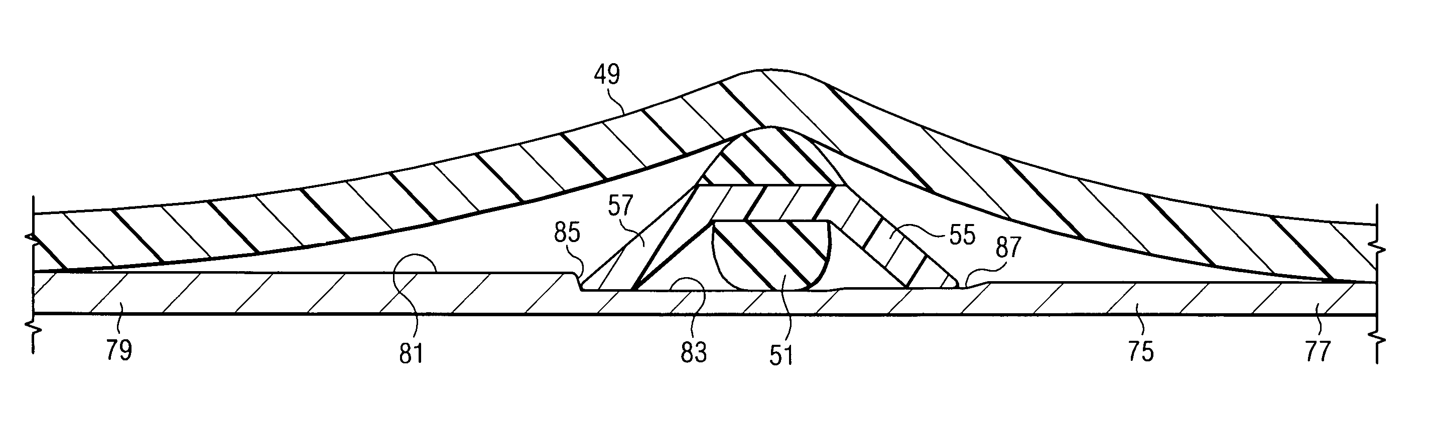
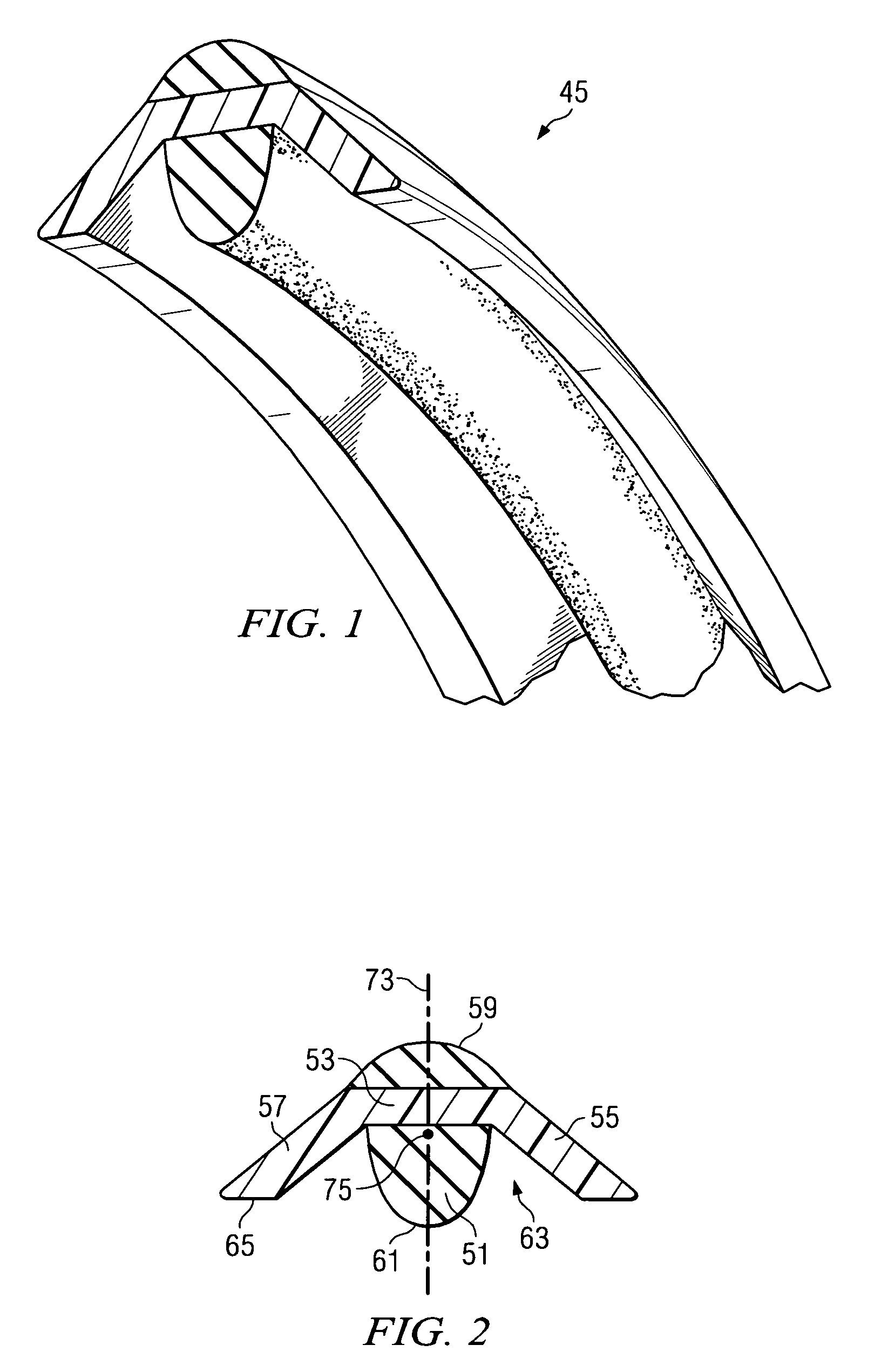
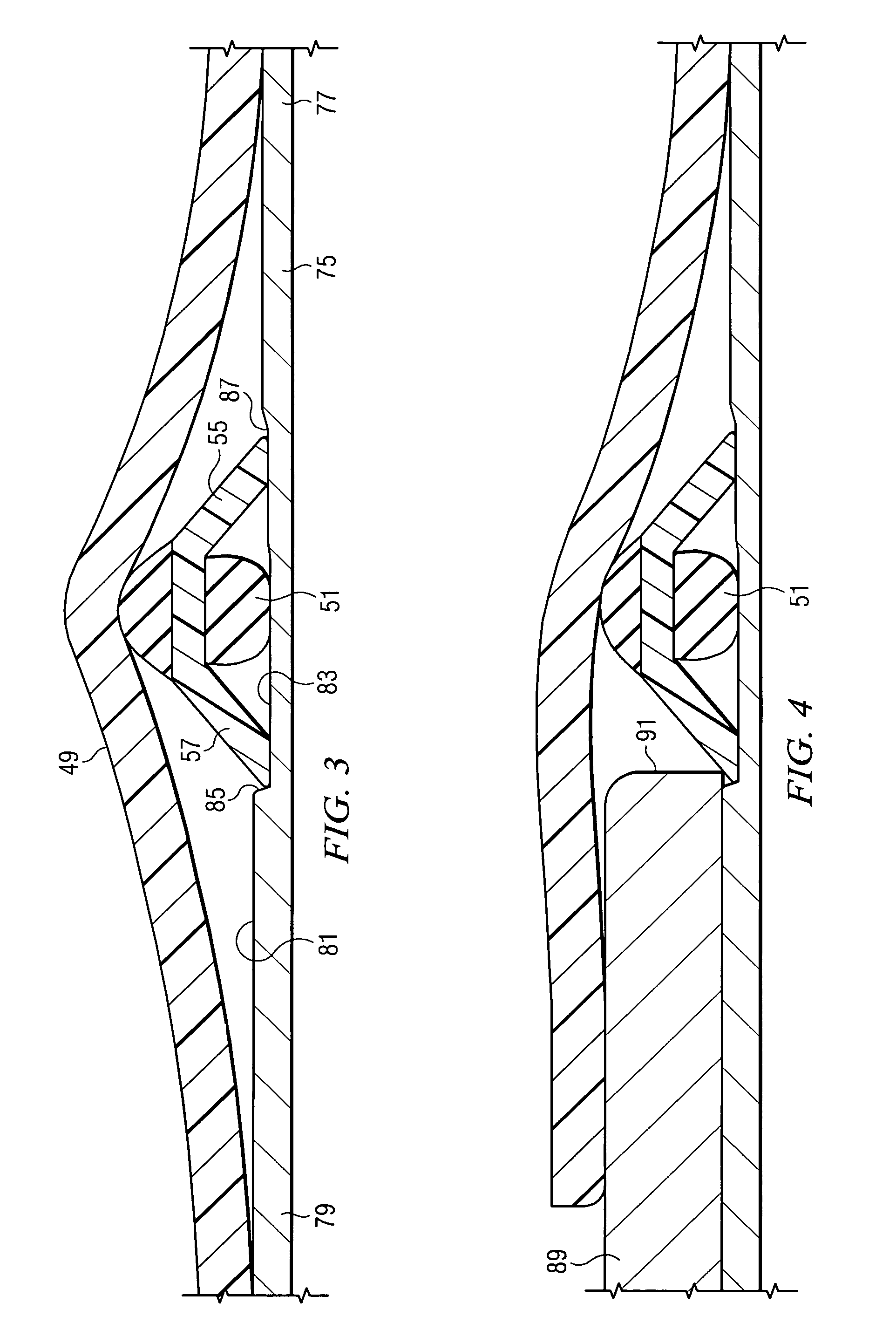
[0030]The primary advantages of the present invention can perhaps be best understood with reference to a simplified discussion of the prior art Rieber pipe belling process and with reference to FIGS. 6-9 of the drawings. FIG. 6 shows a section of a conventional elastomeric sealing...


PUM

PropertyMeasurementUnit
radial diameteraaaaaaaaaa
elastomericaaaaaaaaaa
resilientaaaaaaaaaa

Abstract

An sealing gasket is shown for use in forming joints of plastic pipe. The gasket has a bulbous region which is bisected by a planar region which forms a pair of oppositely extending wing-like flaps. These features of the gasket allow it to be more reliably seated on the working mandrel used to bell a female, thermoplastic pipe end. The wing-like flap portions of the gasket form wiper surfaces for a subsequently installed male, spigot pipe end as the joint is formed.

Description

CROSS-REFERENCE TO RELATED APPLICATION[0001]The present application claims priority from earlier filed provisional application Ser. No. 60 / 933,542, filed Jun. 6, 2007, entitled “Plastic Pipe Gasket and Process for Belling Plastic Pipe,” by inventors Gerardo Darce and Randall Chinchilla.BACKGROUND OF THE INVENTION[0002]1. Field of the Invention[0003]The present invention relates generally to sealing systems for thermoplastic pipes and, more specifically, to an improved pipe gasket and to an improved belling process for installing a gasket in a socket end of a thermoplastic pipe.[0004]2. Description of the Prior Art[0005]Pipes formed from thermoplastic materials including polyethylene and PVC are used in a variety of industries. In forming a joint between sections of pipe, the spigot or male pipe end is inserted within the female or socket pipe end. An annular, elastomeric ring or gasket is typically seated within a groove formed in the socket end of the thermoplastic pipe. As the spi...

Claims


Application Information

Patent Timeline
Patent Type & Authority Patents(United States)
IPC IPC(8): F16L21/02F16L17/03
CPCB29C57/025F16L17/035
Inventor DARCE, GERARDOCHINCHILLA, RANDALL
Owner S & B TECHN PRODS
Why Eureka
Try Eureka