
Fragmented slab lifting apparatus and method

a technology of lifting apparatus and fragmented slabs, which is applied in the direction of hoisting equipment, ways, constructions, etc., can solve the problems of affecting the affecting the safety of workers, etc., to achieve the effect of facilitating proper positioning of the slab lifting apparatus

Active Publication Date: 2013-06-11
KNAPP RONALD A
View PDF26 Cites 10 Cited by
  • Summary
  • Abstract
  • Description
  • Claims
  • Application Information

AI Technical Summary

Benefits of technology

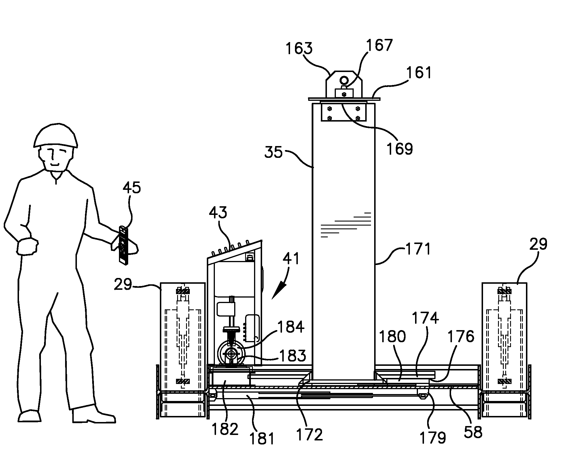
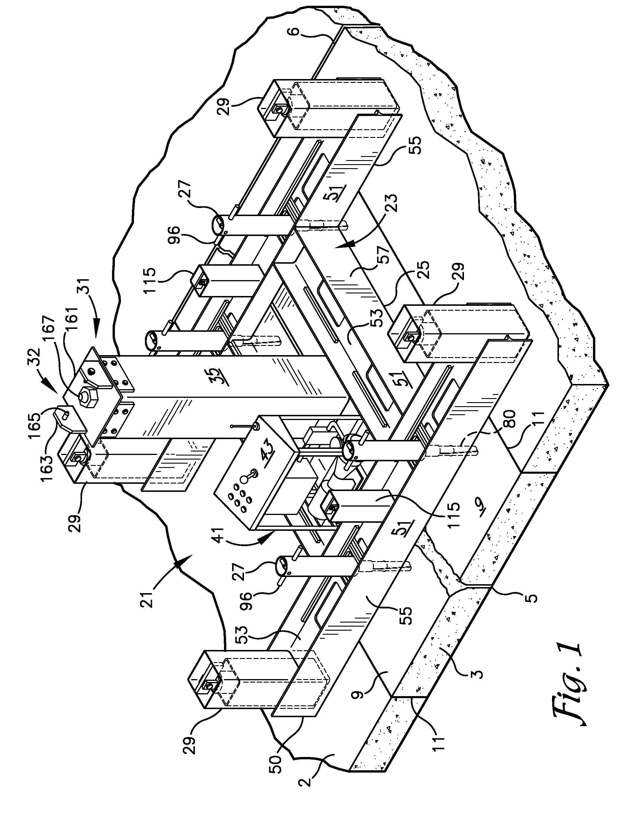
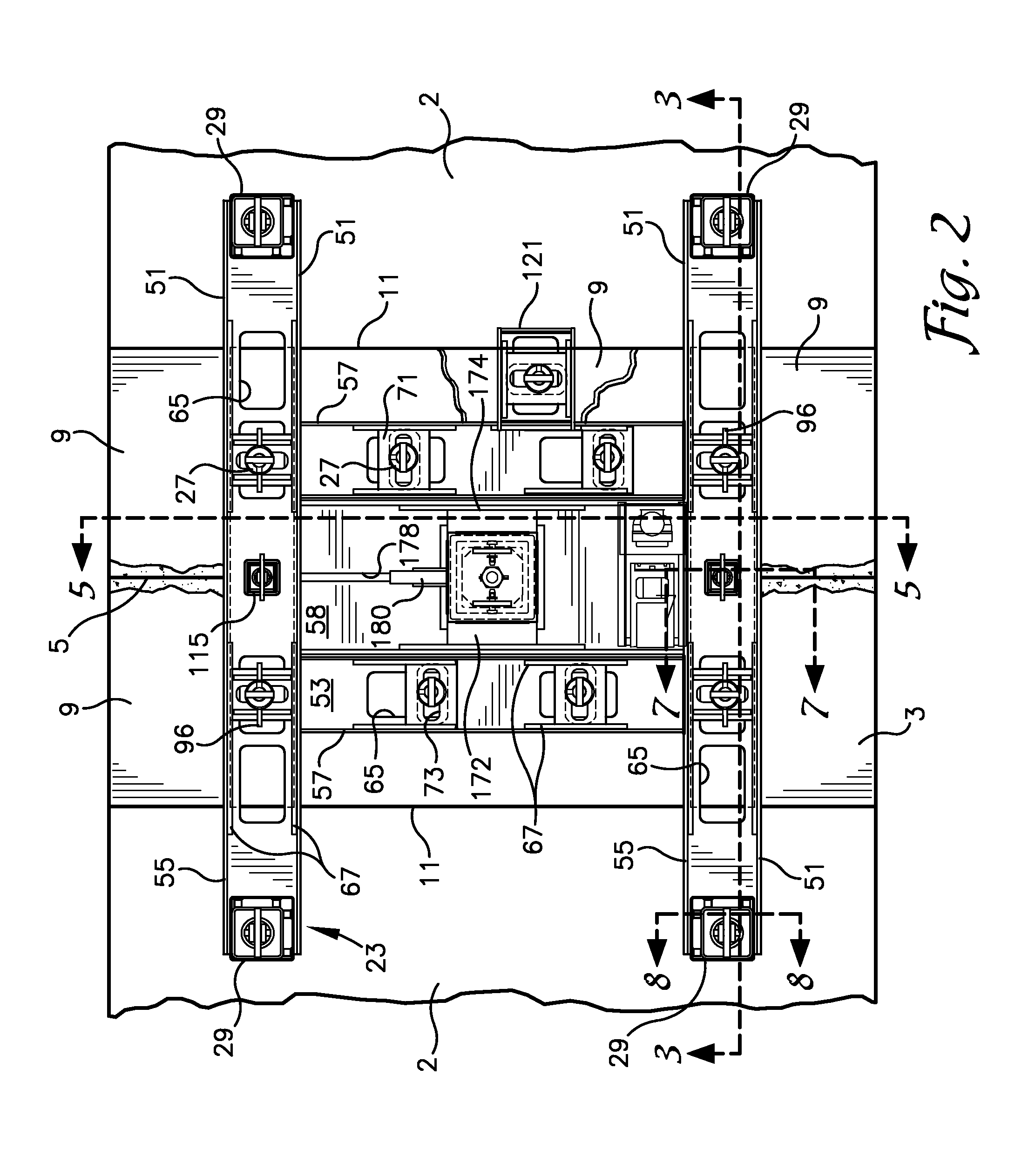
The slab lifting apparatus is designed to safely and easily lift a fragmented slab upward and out from between sections of a concrete slab. It includes a planar support and at least two jacks that engage the surface of the concrete slab on either side of the fragmented slab. A plurality of securement pins is insertable into holes in the fragments and expandable within the holes to secure them to the support. The jacks then lift the planar support and the secured fragments upward relative to the concrete slab. A lift connector is also provided for connecting to an excavator or other lifting device to move the slab lifting apparatus. The telescoping assembly allows for rotation of the slab lifting apparatus and the attached fragmented slab. Overall, the slab lifting apparatus provides a safe and efficient method for lifting and positioning fragmented slabs in construction projects.

Problems solved by technology

Damage at the lateral control joints 5, typically starts with chipping and spawling of the edges of the joint 5, forming a small depression which then grows as tires continuously pound against the defect and water seeps into the cracks therein and freezes further expanding the defects.
Lifting a cracked and fragmented section 3 using a harness connected to locking pins without the load shifting and causing damage to the edge remaining slab is very difficult requiring additional labor to help guide the damaged section from between the adjacent sections of the remaining slab and at a very slow pace.
Even then, the crew may not be able to prevent damage due to shifting of the load.
However, the system disclosed in the Smith '566 patent relies on the use of cables or straps connected between the frame and an overhead crane or the like for lifting the stabilized slab from the adjacent sections of the concrete road which, as discussed, can still result in damage to the edges of the adjacent road.

Method used


Image

  • Fragmented slab lifting apparatus and method
  • Fragmented slab lifting apparatus and method
  • Fragmented slab lifting apparatus and method

Examples


Embodiment Construction

[0032]As required, detailed embodiments of the present invention are disclosed herein; however, it is to be understood that the disclosed embodiments are merely exemplary of the invention, which may be embodied in various forms. Therefore, specific structural and functional details disclosed herein are not to be interpreted as limiting, but merely as a basis for the claims and as a representative basis for teaching one skilled in the art to variously employ the present invention in virtually any appropriately detailed structure. The drawings constitute a part of this specification and include exemplary embodiments of the present invention and illustrate various objects and features thereof.

[0033]Certain terminology will be used in the following description for convenience in reference only and will not be limiting. For example, the words “upwardly,”“downwardly,”“rightwardly,” and “leftwardly” will refer to directions in the drawings to which reference is made. The words “inwardly” a...


PUM


Abstract

A slab jack assembly for raising a fragmented slab from between sections of a concrete slab from which the fragmented slab is cut comprises a planar support positionable on top of the fragmented slab. Jacks are mounted on opposite sides of the planar support to engage an upper surface of the concrete slab. Securement pins mounted on the planar support are insertable into holes bored in the plurality of fragments in the fragmented slab and expandable within the holes to secure the fragments to the planar support. The first and second jacks are then operable to lift the planar support and fragments upward relative to the concrete slab.

Description

FIELD OF THE INVENTION[0001]The present invention is directed to a lifting device used in the repair of concrete roads which lifts out damaged sections of the concrete that have been cut from the surrounding road.BACKGROUND OF THE INVENTION[0002]Referring to the section of road shown in the drawings, a common practice for repairing damaged sections of concrete slabs 2 forming the road is to cut out and remove a damaged section 3 and pour a concrete patch in the remaining hole. The area around lateral control joints 5 formed in the slabs 2 which have degraded over time are areas that are commonly in need of repair. The concrete slab 2 forming a road is typically poured as a generally continuous slab. The slab may be approximately nine to twelve inches thick. Saw cuts are then cut into the slab 2, commonly about one third of the thickness of the pavement, to provide an area of weakness at which cracks will naturally form in the slab 2. Longitudinal joints 6 are formed longitudinally a...

Claims


Application Information

Patent Timeline
Patent Type & Authority Patents(United States)
IPC IPC(8): E01C23/10
CPCE01C23/06B66C19/02E01C23/12
Inventor KNAPP, RONALD A.
Owner KNAPP RONALD A
Learn More