Illuminated directional laser probe

a laser probe and illumination technology, applied in the field of microsurgical equipment, can solve the problems of inability to achieve optimal delivery of illumination light and laser light to the surgical site at the anterior or forward portion of the retina, and the limitations of prior art illumination instruments and laser instruments described abov

Active Publication Date: 2011-12-13
SYNERGETICS
View PDF34 Cites 111 Cited by
  • Summary
  • Abstract
  • Description
  • Claims
  • Application Information

AI Technical Summary

Benefits of technology

A finger actuator is mounted in the handle cavity for forward movement toward the handle distal end, and for opposite rearward movement toward the opposite proximal end of the handle. In the first embodiment of the instrument, the finger actuator is connected to the tip. Movement of the finger actuator in the rearward direction causes the tip distal end to move toward the handle distal end and causes distal end portions of the illumination optic fiber and the laser optic fiber to be extended from the tip distal end. Movement of the finger actuator in the forward direction causes the tip to be extended from the handle distal end and causes the distal ends of both the illumination optic fiber and the laser optic fiber to be retracted into the interior bore of the tip.
A connection is provided between the illumination optic fiber and the laser optic fiber adjacent the distal ends of the illumination optic fiber and the laser optic fiber. The connection prevents relative movement between the illumination optic fiber and the laser optic fiber adjacent their distal ends.
In addition, at least one, and possibly both, of the first tube and second tube are constructed of a shape memory material that is formed in a curved or bent configuration. An example of a shape memory material is nitinol. The curved configurations of both the first tube and second tube cause the respective illumination optic fiber and laser optic fiber to gradually move through a curved path as the finger actuator is moved toward the rearward position on the handle and the distal end portions of the illumination optic fiber and laser optic fiber are extended from the tip distal end. By spacing the welds or adhesive along the lengths of the first and second tubes, the connection between the illumination optic fiber and the laser optic fiber is prevented from breaking apart as the illumination optic fiber and laser optic fiber move through their curved configurations. When the finger actuator is moved toward the forward position causing the rigid tip to be extended from the handle, the tip causes the illumination optic fiber and laser optic fiber to be straightened as the distal ends of the illumination optic fiber and laser optic fiber are moved back into the interior bore of the tip.
In a second embodiment of the instrument, a single metal tube is provided on the illumination optic fiber adjacent the illumination optic fiber distal end, and on the laser optic fiber adjacent the laser optic fiber distal end. The single metal tube is the connection between the illumination optic fiber and the laser optic fiber that prevents relative movement between the illumination optic fiber and the laser optic fiber adjacent their distal ends. The single metal tube is constructed of a shape memory material that is formed in a curved or bent configuration. The curved configuration of the single metal tube causes the illumination optic fiber and the laser optic fiber to gradually move through a curved path as the finger actuator is moved toward the rearward position on the handle and the distal end portions of the illumination optic fiber and laser optic fiber are extended from the tip distal end. When the finger actuator is moved toward the forward position causing the rigid tip to be extended from the handle, the tip causes the illumination optic fiber and the laser optic fiber to be straightened as the distal ends of the illumination optic fiber and laser optic fiber are moved back into the interior of the tip.

Problems solved by technology

The above-described ophthalmic surgery procedures are disadvantaged in that they require at least two incisions in the eye, increasing the trauma to the eye.
Furthermore, the prior art illumination instrument and the prior art laser instrument described above are limited to directing illumination light and laser light to only the posterior area of the eye interior.
In using instruments of this type, the optimal delivery of illumination light and laser light to a surgical site at an anterior or forward portion of the retina cannot be achieved.

Method used


Image

  • Illuminated directional laser probe
  • Illuminated directional laser probe
  • Illuminated directional laser probe

Examples


first embodiment

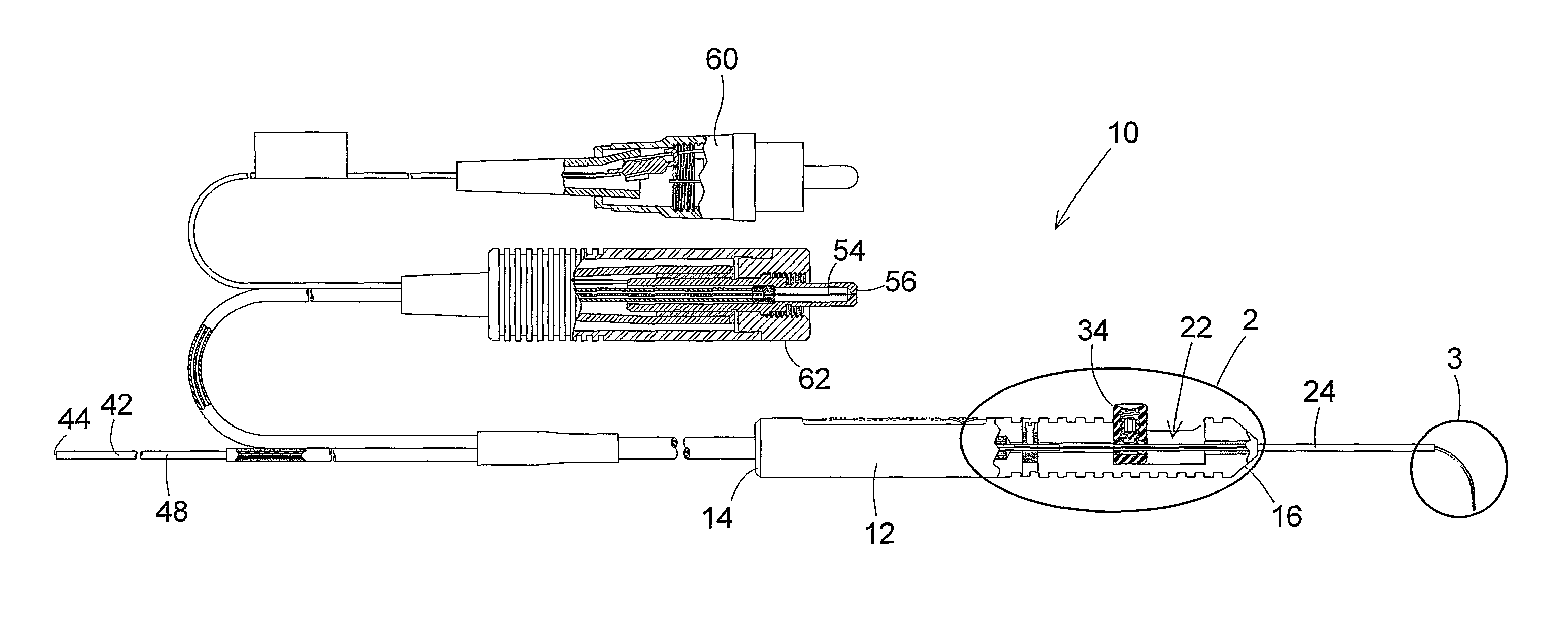
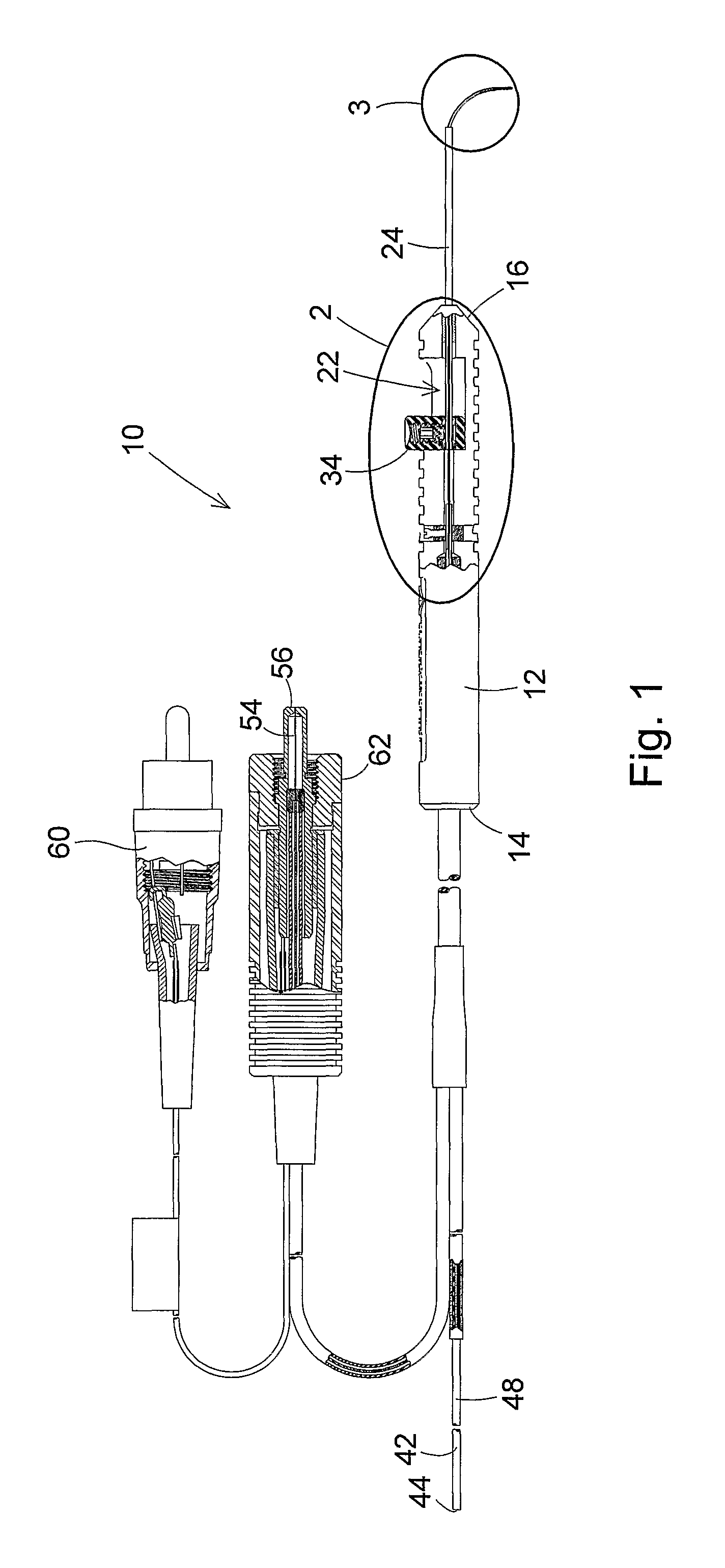
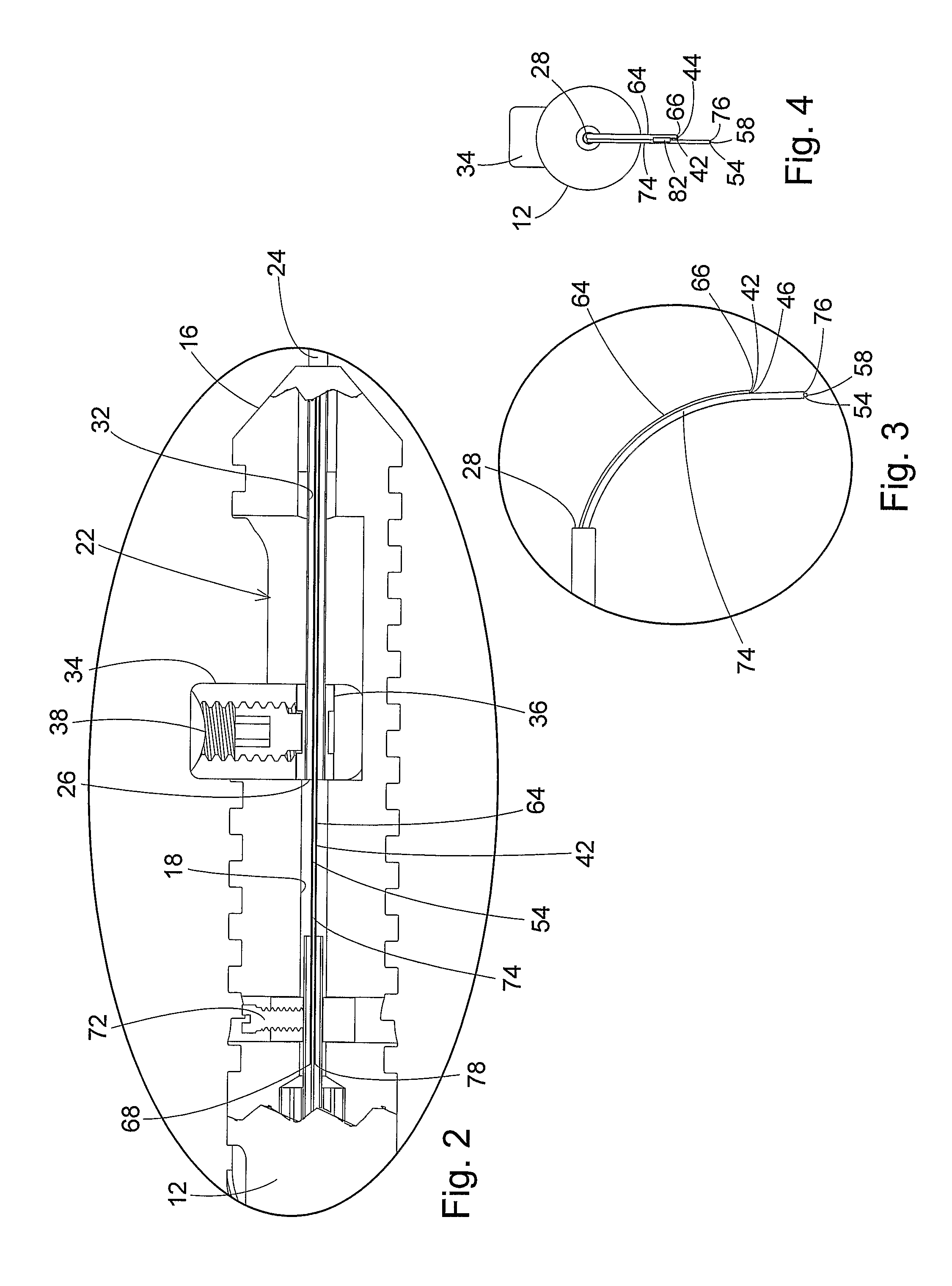
In the operation of this first embodiment of the probe 10, movement of the finger actuator 34 in the rearward direction through the handle cavity 22 causes the tip distal end 28 to move toward the handle distal end 16. This causes the distal end portions of the illumination optic fiber 42 contained in the first tube 64 and the laser optic fiber 54 contained in the second tube 74 to be extended from the tip distal end 28. As the first tube 64 and second tube 74 extend outwardly from the tip distal end 28, the curved configurations of the tubes cause the illumination optic fiber 42 and the laser optic fiber 54 to gradually bend together toward the bent or curved configurations of the fibers shown in FIGS. 1, 3, and 4.

Movement of the finger actuator 34 in the forward direction through the handle cavity 22 causes the tip 24 to be extended from the handle distal end 16. This causes the first tube 64 containing the illumination optic fiber 42 and the second tube 74 containing the laser op...

second embodiment

A second embodiment of the illuminated directional laser probe is shown in FIGS. 8-15. the probe 90 employs many of the same component parts of the previously described embodiment of the probe 10. The common parts are identified in FIGS. 8-15 with the same reference numbers employed in identifying the earlier described probe 10, with the reference numbers being followed by a prime (′). Because the same component parts of the two probes 10, 90 have been described previously, they will not be described again in describing the construction of the second embodiment of the probe 9 shown in FIGS. 8-15.

The primary difference between the probe 90 shown in FIGS. 8-15 and the previously described probe 10 is that the first tube 64 and second tube 74 are absent from the second embodiment of the probe 90. Instead, a single tube 92 surrounds and contains portions of the illumination optic fiber 42′ and the laser optic fiber 54′ adjacent the respective distal ends 46′, 58′ of the two fibers. The ...


PUM


Abstract

An ophthalmic surgery illuminated directional laser probe has a handle and a rigid tubular tip projecting from the handle, and has an illumination optic fiber and a laser optic fiber that extend through the handle and the tip. A mechanism on the handle is operable to extend distal ends of the illumination optic fiber and the laser optic fiber from the distal end of the instrument tip, and to retract the distal ends of the illumination optic fiber and the laser optic fiber back into the interior of the tip. At least one of the distal ends of the illumination optic fiber and the laser optic fiber is held in a curved configuration. The distal ends of the illumination optic fiber and the laser optic fiber are secured to each other, whereby both the illumination optic fiber and the laser optic fiber curve into a bent configuration as the distal ends of the illumination optic fiber and the laser optic fiber are extended from the distal end of the instrument tip.

Description

BACKGROUND OF THE INVENTION(1) Field of the InventionThe present invention pertains to a microsurgical apparatus primarily used in ophthalmic surgery procedures. In particular, the invention pertains to an illuminated directional laser probe having a handle and a rigid tubular tip projecting from the handle, and having an illumination optic fiber and a laser optic fiber that extend through the handle and the tip. A mechanism on the handle is operable to cause distal ends of the illumination optic fiber and the laser optic fiber to be extended from the distal end of the tubular tip, and to cause the distal ends of the illumination optic fiber and the laser optic fiber to be retracted back into the tubular tip. At least one of the distal ends of the illumination optic fiber and the laser optic fiber is held in a curved configuration. The distal ends of the illumination optic fiber and the laser optic fiber are secured to each other, whereby both the illumination optic fiber and the la...

Claims


Application Information

Patent Timeline
Patent Type & Authority Patents(United States)
IPC IPC(8): A61B18/20
CPCA61B18/22A61B2018/00196A61B2019/5206A61B2090/306A61B2018/2288A61F9/008
Inventor SCHELLER, GREGG D.AULD, MICHAEL D.NADOLSKI, TIMOTHY J.
Owner SYNERGETICS
Why Eureka
Try Eureka