
Apparatus for delivering paint to a paint roller directly from a paint can with a compartment for holding a paint brush

a paint roller and compartment technology, applied in the field of paint rollers, can solve problems such as being unsuitable for the purposes of delivering paint to the paint rollers

Inactive Publication Date: 2011-12-20
MCLAUGHLIN THOMAS
View PDF14 Cites 21 Cited by
  • Summary
  • Abstract
  • Description
  • Claims
  • Application Information

AI Technical Summary

Benefits of technology

[0018]AN OBJECT of the present invention is to provide an apparatus for delivering paint to a paint roller directly from a paint can with a compartment for holding a paint brush that avoids the disadvantages of the prior art.
[0019]ANOTHER OBJECT of the present invention is to provide an apparatus for delivering paint to a paint roller directly from a paint can with a compartment for holding a paint brush that is simple and inexpensive to manufacture.
[0020]STILL ANOTHER OBJECT of the present invention is to provide an apparatus for delivering paint to a paint roller directly from a paint can with a compartment for holding a paint brush that is simple to use.
[0021]BRIEFLY STATED, STILL YET ANOTHER OBJECT of the present invention is to provide an apparatus for delivering paint to a paint roller directly from a paint can with a compartment for holding a paint brush which comprises a housing. A mechanism is for securing the housing to an exterior surface of a cylindrical side wall of the paint can. A roller wiper component is also provided. Another mechanism is for mounting the roller wiper component on the housing to extend over the paint can. After a roller cover of the paint roller is charged with paint contained in the paint can, excessive paint on the roller cover of the paint roller will be removed therefrom by the roller wiper component to safely drip back into the paint can.

Problems solved by technology

Furthermore, even though these innovations may be suitable for the specific individual purposes to which they address, accordingly, they would not be suitable for the purposes of the present invention as heretofore described.

Method used


Image

  • Apparatus for delivering paint to a paint roller directly from a paint can with a compartment for holding a paint brush
  • Apparatus for delivering paint to a paint roller directly from a paint can with a compartment for holding a paint brush
  • Apparatus for delivering paint to a paint roller directly from a paint can with a compartment for holding a paint brush

Examples


Embodiment Construction

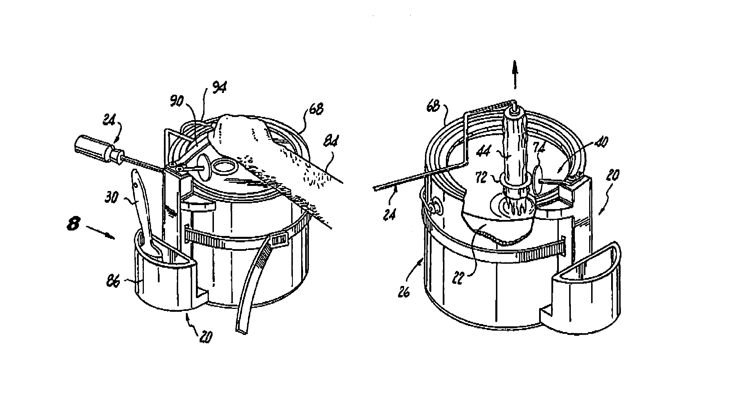
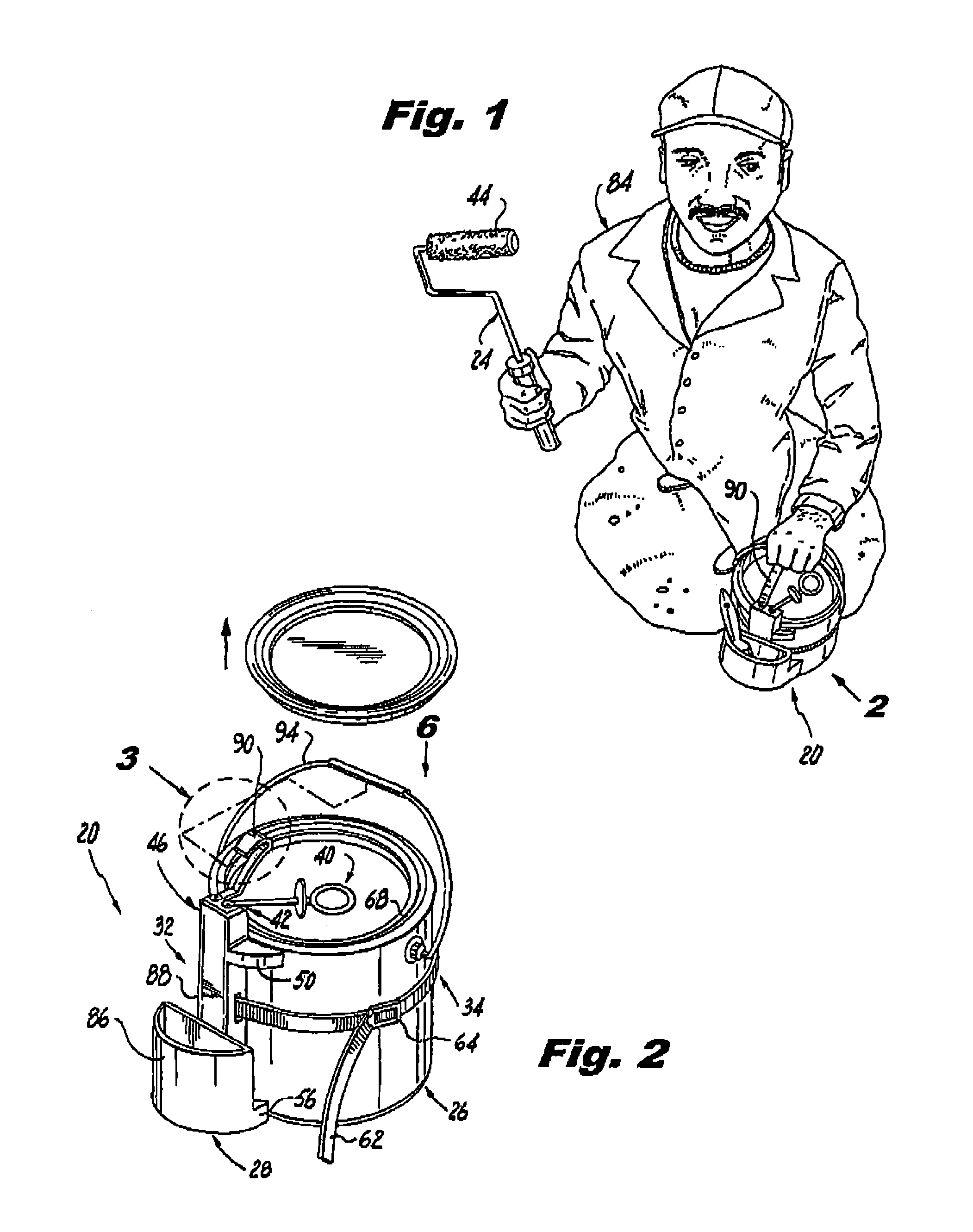
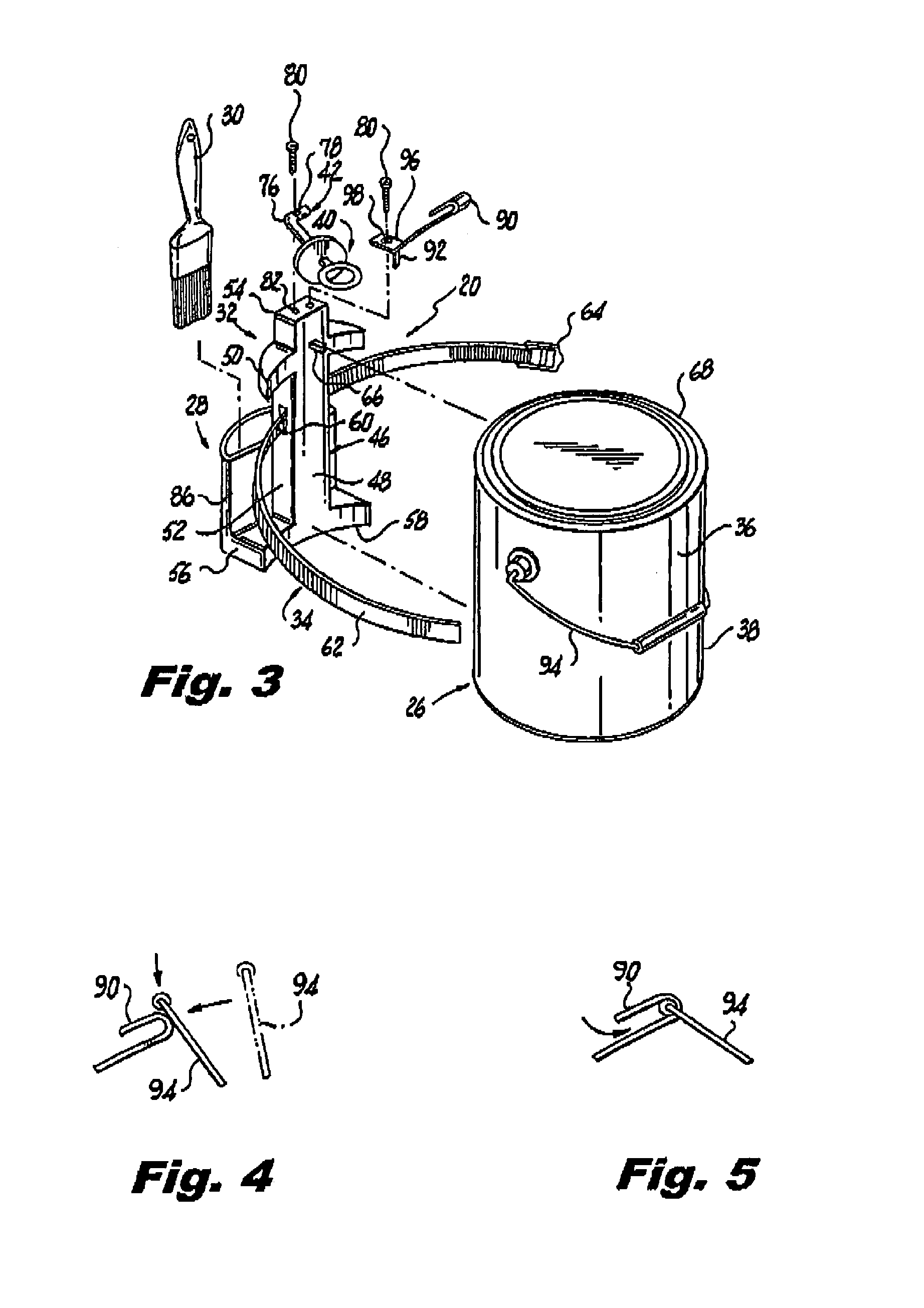
[0076]Referring now to the figures, in which like numerals indicate like parts, and particularly to FIGS. 1 through 12, which are a diagrammatic perspective view of an embodiment of the present invention installed on a paint can and ready for use by a painter; an enlarged diagrammatic perspective view taken in the direction of arrow 2 in FIG. 1, with the lid exploded from the paint can; an exploded diagrammatic perspective view showing the present invention ready to be installed on the paint can; a diagrammatic side elevational view, of the area enclosed in the dotted circle indicated by arrow 3 in FIG. 2, showing the bail disengaged from the spring hook clip; a diagrammatic side elevational view, of the area enclosed in the dotted circle indicated by arrow 3 in FIG. 2, showing the bail engaging the spring hook clip; a diagrammatic top elevational view taken in the direction of arrow 6 in FIG. 2, with the paint can broken away, showing how the roller wiper component will be mounted ...


PUM


Abstract

An apparatus for delivering paint to a paint roller directly from a paint can with a compartment for holding a paint brush which comprises a housing. A mechanism is for securing the housing to an exterior surface of a cylindrical side wall of the paint can. A roller wiper component is also provided. Another mechanism is for mounting the roller wiper component on the housing to extend over the paint can. After a roller cover of the paint roller is charged with paint contained in the paint can, excessive paint on the roller cover of the paint roller will be removed therefrom by the roller wiper component to safely drip back into the paint can.

Description

BACKGROUND OF THE INVENTION[0001]1. Field of the Invention[0002]The present invention relates to a paint roller, and more particularly, an apparatus for delivering paint to a paint roller directly from a paint can with a compartment for holding a paint brush.[0003]2. Description of the Prior Art[0004]Numerous innovations for paint equipment have been provided in the prior art that will be described. Even though these innovations may be suitable for the specific individual purposes to which they address, however, they differ from the present invention.[0005]A FIRST EXAMPLE, U.S. Pat. No. 3,809,484, Issued on May 7, 1974, to Bradshaw teaches a convenient and efficient supply device for delivering paint from a conventional container through a line which includes a first flexible hose, a manual pump, a second flexible hose, and a manifold, to the exterior of a conventional paint roller. The manifold can be used in either of two operating positions at opposite sides of the plane defined ...

Claims


Application Information

Patent Timeline
Patent Type & Authority Patents(United States)
IPC IPC(8): A46B11/00A46B17/08
CPCB44D3/123B44D3/128A46B17/08A46B2200/202
Inventor MCLAUGHLIN, THOMAS
Owner MCLAUGHLIN THOMAS
Learn More