Emergency cellular telephone system

a cellular telephone system and emergency technology, applied in the field of emergency cellular telephone systems, can solve the problems of not being able to tell the 911 operator their exact location, not being able to solve the problem of no, and not being able to know which door leads to the caller, so as to facilitate the caller's finding, avoid injury, and be carried or worn conveniently

Inactive Publication Date: 2011-12-20
BLUM ALVIN S
View PDF24 Cites 10 Cited by
  • Summary
  • Abstract
  • Description
  • Claims
  • Application Information

AI Technical Summary

Benefits of technology

This invention provides both a conventional cellular telephone operating system as well as a special emergency telephone operation along with means for alerting those outside a building that an emergency call has been made from within the building. It requires neither special installation nor monthly expenditure outside of the original cellular telephone service fees. A conventional cellular telephone or handset has one radio frequency connection. The handset contains a rechargeable battery that is periodically recharged in a separate charger connected to a house power outlet. A user in need of emergency help may call the emergency telephone number such as 911 and tell the operator the location of the caller and other information. The above is true of conventional cordless telephones. The handset of the invention has a first broad face with the usual features provided by a cellular telephone. In addition to the usual handset features, this one has a reverse side featuring a large emergency button that calls 911. The handset of this invention also has a second radio connection. It is a short range radio connection to an alerting device that attaches to the inside glass surface of a window with one or more suction cups. The alerting device is connected to an inside house power outlet. When the alerting device receives the short range radio frequency signal from actuation of the emergency button, it emits a light signal to the outside through the window indicating that an emergency call has been made from the premises. It may also provide an audible signal. The alerting device is mounted on the inside glass surface of a window preferably at the front of the premises. This enables the responders to more easily find the caller. The handset is designed to be compact so as to be conveniently carried or worn, for example, as a pendant around the neck or clipped to the clothes with the emergency button outermost. When an ordinary call comes in, the user need not rush to a phone, because it is at hand. This avoids injury from rushing to answer a call. In the event of a fall or emergency anywhere in the residence, the user need not travel to get help. The alerting device may be provided with another feature. When the alerting device receives a signal indicating that the emergency button has been actuated, it may send a signal back to the handset. This signal may actuate a recorded message that is sent out on the cellular network indicating the request for help, the location of the device, and other information such as, “I have diabetes. My neighbor at apartment 203 has a key”. If the user is unable to speak, the recorded message will suffice. Since this message will not be given when the handset is beyond the range of the short range radio signal and the premises, there is no danger of confusing the responders by having them go to a vacant location. The recharge station is best provided at the bedside to provide the handset at hand while in bed, and to ensure regular recharging.

Problems solved by technology

They may not be able to tell the 911 operator their exact location when they are at home.
Even when a call is successful and responders reach the address given them, they may not be sure of which door leads to the caller, such as in an apartment building.
If no one answers, they may be reluctant to break in, and they may leave without rendering any assistance.
It does not solve the problem of no one answering a knock on the door.
If they are renters, they may not be permitted to make changes such as holes through the wall.
Even when the responders reach the address given them, they may not be sure of which door leads to the caller, such as in an apartment building.
If no one answers, they may be reluctant to break in, and they may leave without rendering any assistance.

Method used


Image

  • Emergency cellular telephone system
  • Emergency cellular telephone system
  • Emergency cellular telephone system

Examples


Embodiment Construction

This invention now will be described more fully hereinafter with reference to the accompanying drawing, in which exemplary embodiments are shown. This invention may, however, be embodied in many different forms and should not be construed as limited to the embodiments set forth here. Rather, these embodiments are provided so that this disclosure will be thorough and complete, and will fully convey the scope of the invention to those of ordinary skill in the art. Moreover, all statements herein reciting embodiments of the invention, as well as specific examples thereof, are intended to encompass both structural and functional equivalents thereof. Additionally, it is intended that such equivalents include both currently known equivalents as well as equivalents developed in the future.

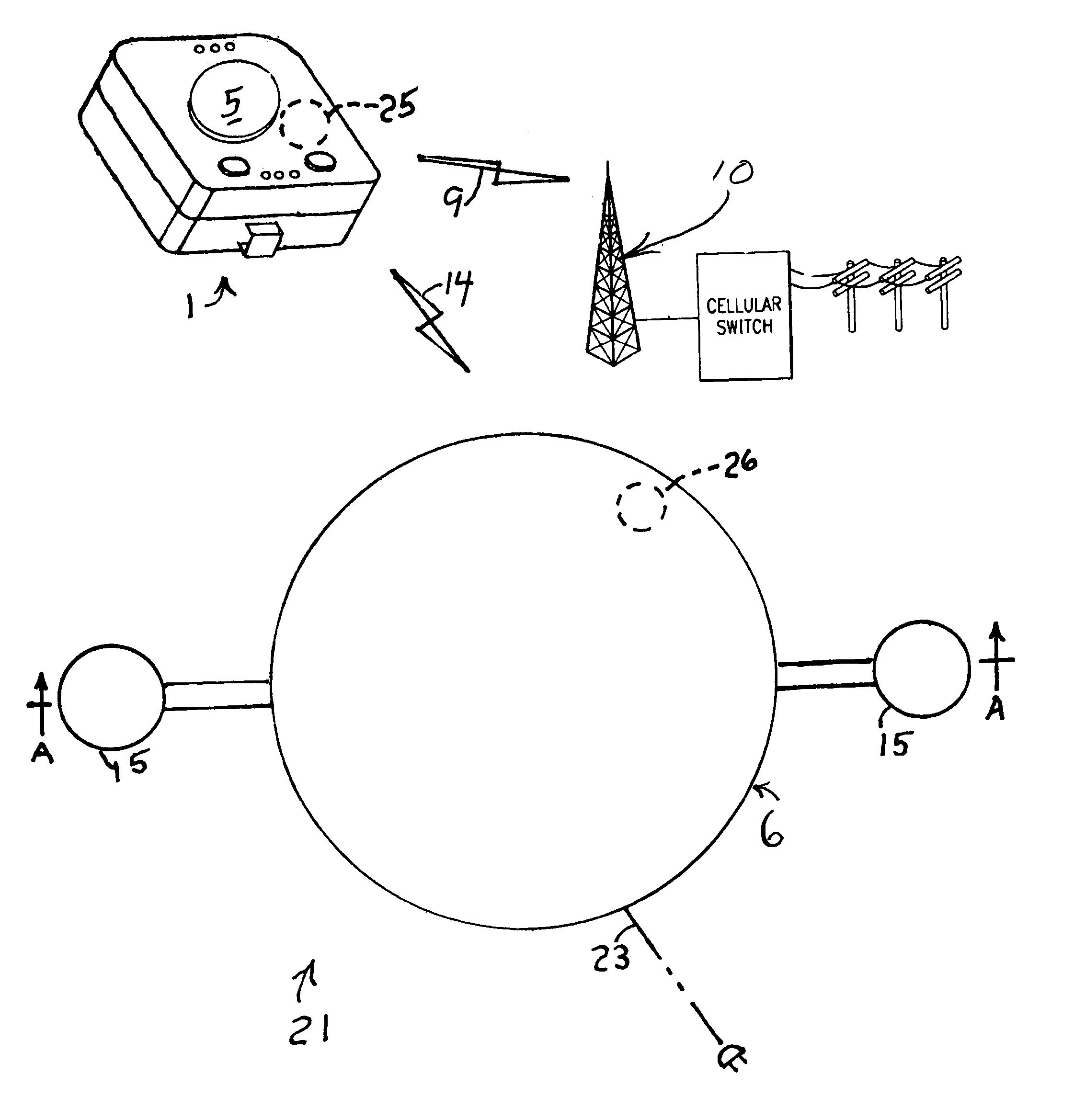
Referring now to the drawing FIGS. 1-7, an emergency cellular telephone system 21 of the invention, as shown diagrammatically in FIG. 1, comprises a remote cellular network 10, a handset 1, and a signalin...


PUM


Abstract

A telephone system includes a user-carried emergency communication system in combination with a cellular telephone. The user-carried handset has a large button on a first face. Pressing the button summons help by automatic connection to the 911 emergency telephone network. It also activates a signaling device mounted on the inside glass surface of a window that illuminates a message that 911 has been called. It may also sound an alarm. A pre-recorded massage may also be sent to the emergency call center. The other face has the functions of a cellular telephone. All elements are within the building, with installation by simply plugging cords into power outlets the same as any cellular phone and mounting the signaling device with suction cups. There are no monthly fees except for the usual cellular phone fee.

Description

BACKGROUND OF THE INVENTIONThe present invention relates generally to a telephone system, and more particularly to a cellular telephone system that provides both conventional cellular telephone operation as well as a special emergency telephone operation. The current emergency service system in operation throughout this country is the 911 emergency service provided by the telephone system. The system has the ability to locate any residence from which a landline telephone call to the 911 number is made. Cellular telephones do not have this feature, although the 911 system may be able to triangulate the call emissions to determine the present location of the caller. Many individuals may find themselves alone in a location that is equipped with only a cellular telephone. If they are incapacitated, they may dial 911 for assistance. They may not be able to tell the 911 operator their exact location when they are at home. Even when a call is successful and responders reach the address giv...

Claims


Application Information

Patent Timeline
Patent Type & Authority Patents(United States)
IPC IPC(8): H04M11/04
CPCG08B25/12H04M11/045
Inventor BLUM, ALVIN S.
Owner BLUM ALVIN S
Why Eureka
Try Eureka