Glasses hinge structure

a technology of hinges and hinges, applied in the field of glasses hinges, can solve the problems of inconvenient assembly, disassembly or replacement of glasses, and achieve the effect of easy manufacturing

Inactive Publication Date: 2011-12-27
CHEN TSUNG WEN
View PDF2 Cites 6 Cited by
  • Summary
  • Abstract
  • Description
  • Claims
  • Application Information

AI Technical Summary

Benefits of technology

[0005]The primary object of the present invention is to provide a glasses hinge structure, which doesn't need a screw to lock the glasses hinge, providing a convenient and easy way for assembly, disassembly or displacement.
[0008]The pivot seat and the pivot of the present invention are integrally formed with the cornel panel of the glasses frame and the glasses foot, respectively, through a mold, which is manufactured with ease. To assemble the present invention, the vertical portion of the pivot is inserted into the vertical trough of the pivot seat, so that the glasses foot and the cornel panel of the glasses frame are hinged together with the pivot seat and the pivot. To disassemble the present invention, the vertical portion of the pivot is retreated from the vertical trough of the pivot seat. It is not necessary to use a tool to assemble, disassemble or replace the glasses, without a screw for connection. This is convenient for a user to replace a desired glasses foot so as to match a different hair style or clothing.

Problems solved by technology

It is necessary to use a tool for tightening or loosening the screw 50, which is very inconvenient to assemble, disassemble or displace the glasses.

Method used


Image

  • Glasses hinge structure
  • Glasses hinge structure
  • Glasses hinge structure

Examples


Embodiment Construction

[0014]Embodiments of the present invention will now be described, by way of example only, with reference to the accompanying drawings.

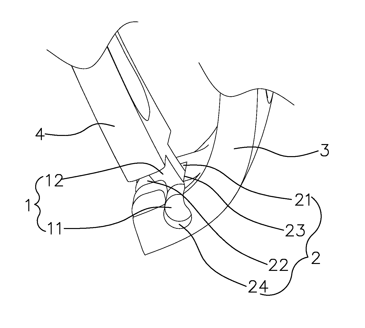
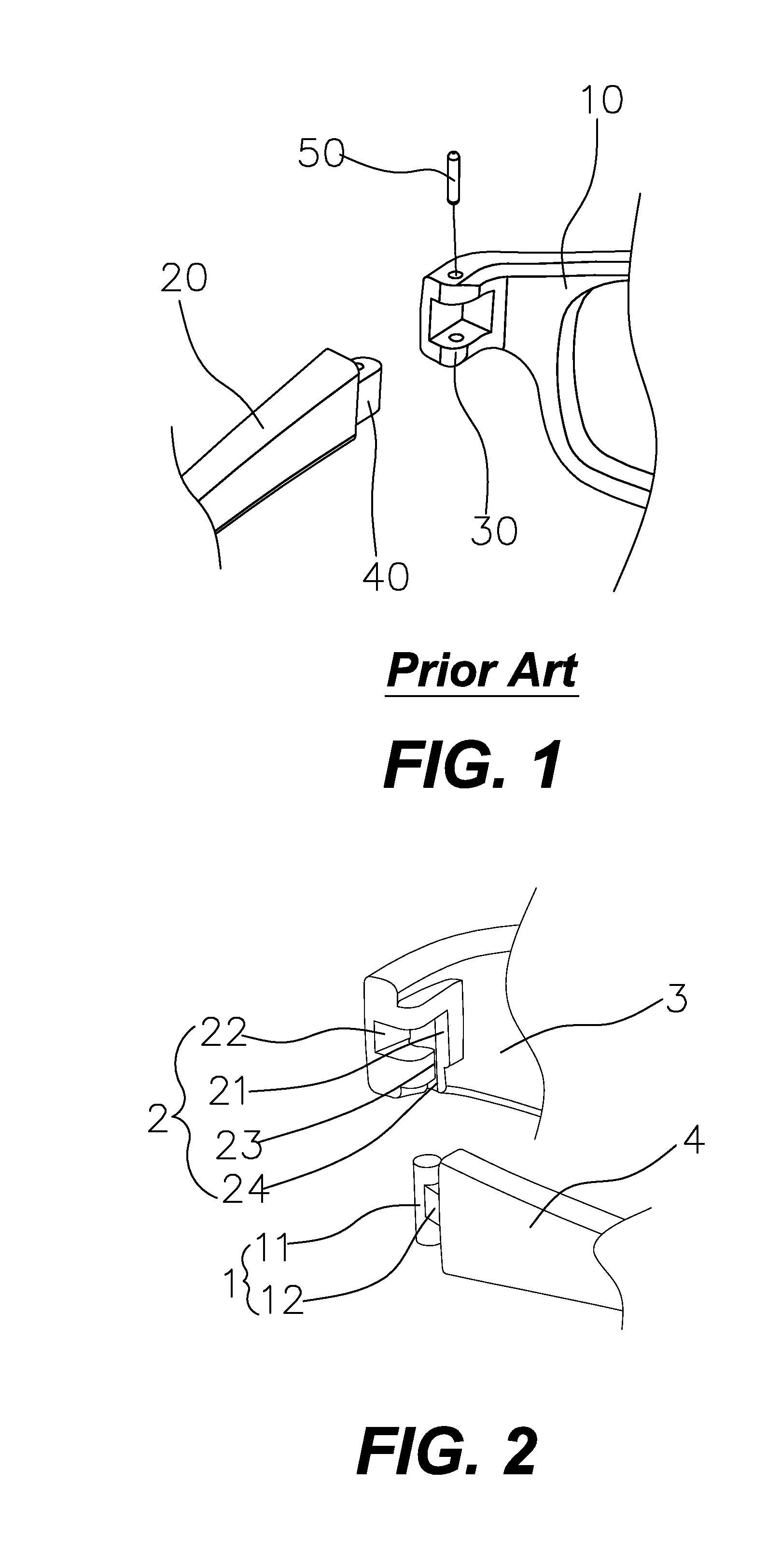
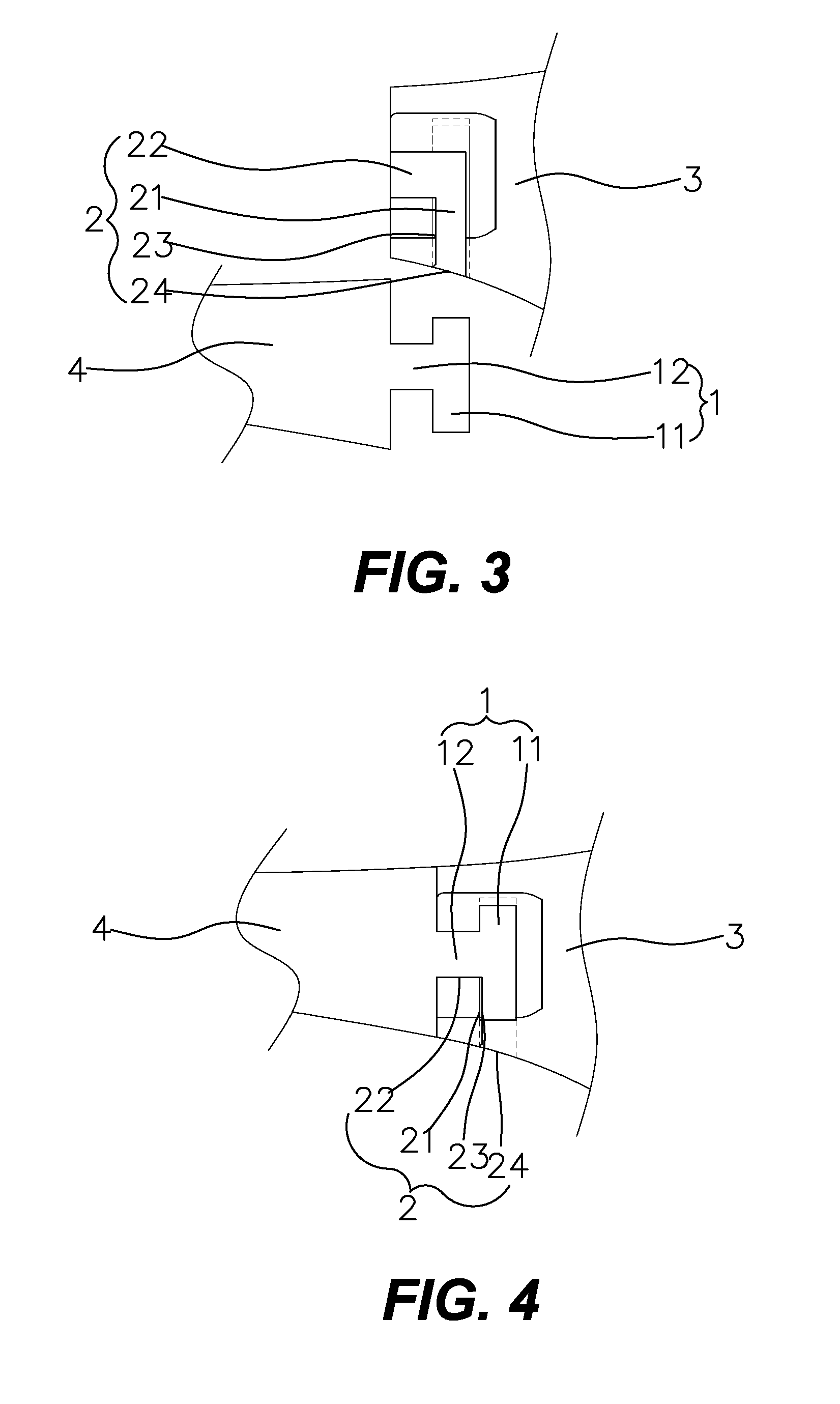
[0015]As shown in FIG. 2, a glasses hinge structure according to a preferred embodiment of the present invention comprises a pivot 1 and a pivot seat 2. The pivot seat 2 and the pivot 1 are integrally formed with a corner panel 3 of a glasses frame and a glasses foot 4, respectively. In the embodiment, the pivot 1 is integrally formed with the glasses foot 4. The pivot 1 has a vertical portion 11 in a cylinder shape and a horizontal connecting portion 12. The vertical portion 11 has a middle section connected with a front end of the horizontal connecting portion 12. The horizontal connecting portion 12 has a rear end connected to the glasses foot 4.

[0016]The pivot seat 2 is integrally formed with the corner panel 3 of the glasses frame. The pivot seat 2 has a vertical trough 21 and a recess 22. The vertical trough 21 is adapted for insertion of the ve...


PUM


Abstract

A glasses hinge structure includes a pivot and a pivot seat. The pivot seat and the pivot are integrally formed with a corner panel of a glasses frame and a glasses foot, respectively. The pivot has a vertical portion in a cylinder shape and a horizontal connecting portion. The vertical portion has a middle section connected with a front end of the horizontal connecting portion. The horizontal connecting portion has a rear end connected to the glasses foot. The pivot seat has a vertical trough and a recess. The vertical trough is adapted for insertion of the vertical portion of the pivot. The recess is interconnected with a middle section of the vertical trough to accommodate the horizontal connecting portion when the glasses foot is extended. The vertical trough has a C-shaped cross-section which has an opening. The opening is less than a diameter of the vertical portion and greater than a width of the horizontal connecting portion. One end of the vertical trough is formed with a notch for the vertical portion to be inserted therefrom.

Description

BACKGROUND OF THE INVENTION[0001]1. Field of the Invention[0002]The present invention relates to a glasses hinge, and more particularly to a glasses hinge structure without using a screw to lock a glasses foot.[0003]2. Description of the Prior Art[0004]As shown in FIG. 1, a conventional glasses hinge structure is composed of a pivot seat 30 of a corner panel 10 of a glasses frame, another pivot seat 40 of a glasses foot 20, and a screw 50. It is necessary to use a tool for tightening or loosening the screw 50, which is very inconvenient to assemble, disassemble or displace the glasses. Accordingly, the inventor of the present invention has devoted himself based on his many years of practical experiences to solve this problem.SUMMARY OF THE INVENTION[0005]The primary object of the present invention is to provide a glasses hinge structure, which doesn't need a screw to lock the glasses hinge, providing a convenient and easy way for assembly, disassembly or displacement.[0006]According...

Claims


Application Information

Patent Timeline
Patent Type & Authority Patents(United States)
IPC IPC(8): G02C5/22
CPCG02C5/2209Y10T16/526
Inventor CHEN, TSUNG-WEN
Owner CHEN TSUNG WEN
Why Eureka
Try Eureka