Probe connector

Inactive Publication Date: 2011-12-27
CHENG UEI PRECISION IND CO LTD
View PDF5 Cites 27 Cited by
  • Summary
  • Abstract
  • Description
  • Claims
  • Application Information

AI Technical Summary

Benefits of technology

[0007]As described above, the two matching fastening portions are engaged with the fastening portions of the insulating housing to avoid the shielding shell falling o

Problems solved by technology

However, the shielding shell is fastened on the insulating housing by means of buckling the inverted hooks in the buckling grooves, the as

Method used


Image

  • Probe connector
  • Probe connector
  • Probe connector

Examples


Embodiment Construction

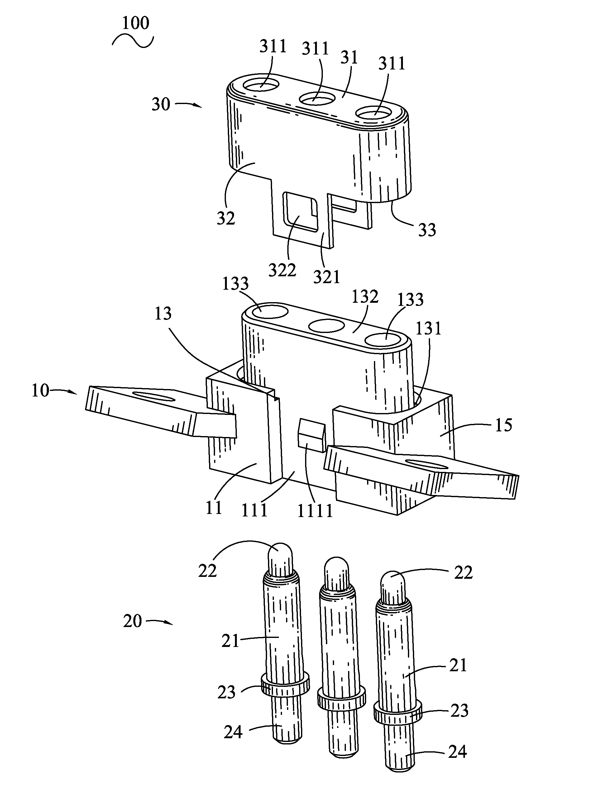
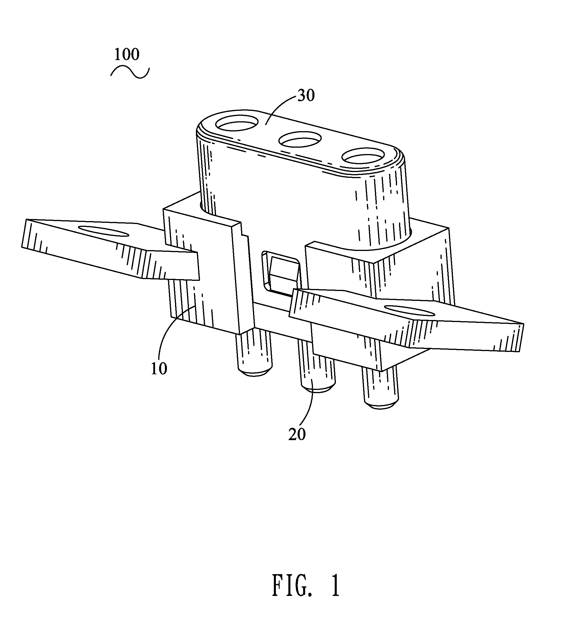
[0012]With reference to FIG. 1, a probe connector 100 according to the present invention includes an insulating housing 10, a plurality of probe pins 20 and a shielding shell 30 mounted to the insulating housing 10 respectively.

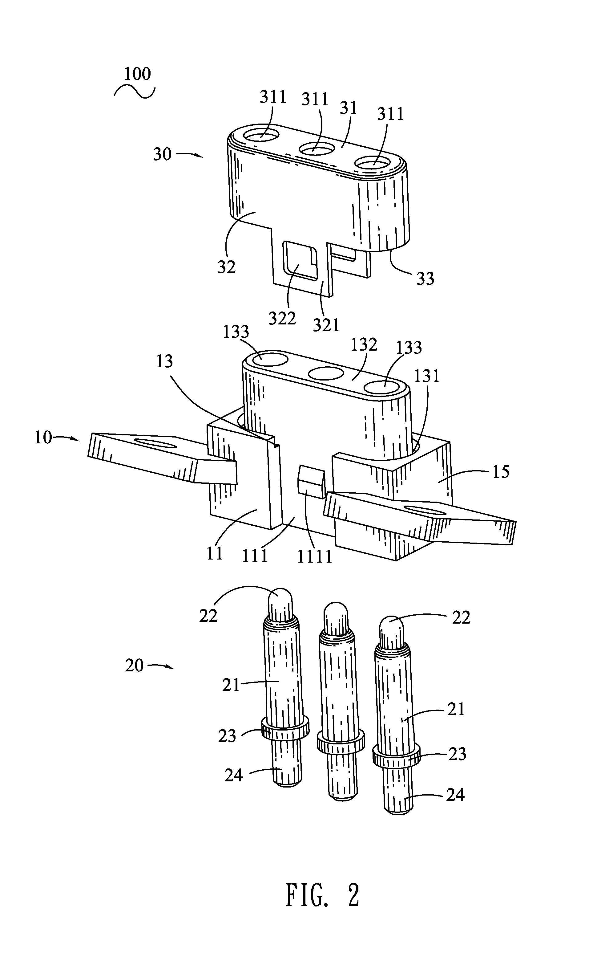
[0013]Referring to FIGS. 2-3, the insulating housing 10 has a base body 15 of rectangular shape. The base body 15 has a front surface 11, a rear surface 12, a top surface 13 and a bottom surface 14. A middle of the top surface 13 of the base body 15 protrudes upward to form a tongue portion 132 of an elliptic shape viewed from a top view. The top surface 13 of the base body 15 defines an elliptical ring-shaped receiving groove 131 circling and adjacent to a bottom of the tongue portion 132. The insulating housing 10 defines a plurality of inserting holes 133 vertically penetrating through the base body 15 and the tongue portion 132. Middles of the front surface 11 and the rear surface 12 are cut off to define a first opening 111 and a second opening 121 passi...


PUM


Abstract

A probe connector includes an insulating housing, a plurality of probe pins and a shielding shell. The insulating housing has a base body and a tongue portion. The insulating housing defines a plurality of inserting holes penetrating through the base body and the tongue portion. Two opposite surfaces of the base body defines two fastening portions. The probe pins are inserted in the inserting holes. The shielding shell has a top plate and a blocking plate extending downward from a periphery of the top plate with an accommodating chamber formed therein. The top plate defines a plurality of matching holes. The tongue portion is inserted in the accommodating chamber with the matching holes aligned with the corresponding inserting holes. Two fastening plates are protruded from two opposite bottom edges of the blocking plate. Each fastening plate has a matching fastening portion thereon for engaging with the fastening portion.

Description

BACKGROUND OF THE INVENTION[0001]1. Field of the Invention[0002]The present invention relates to a probe connector, and more particularly to a probe connector having a shielding shell capable of being assembled to an insulating housing of the probe connector tightly.[0003]2. The Related Art[0004]A traditional probe connector generally includes an insulating housing, a plurality of probe pins and a shielding shell. The insulating housing has a top surface. Two sides of the top surface extend upward and then protrude towards each other to form two inverted hooks facing to each other. The top surface defines a plurality of inserting holes spaced at regular intervals. The probe pins are inserted in the inserting holes respectively. The shielding shell is mounted to the insulating housing and defines a plurality of buckling grooves for buckling the inverted hooks therein.[0005]However, the shielding shell is fastened on the insulating housing by means of buckling the inverted hooks in th...

Claims


Application Information

Patent Timeline
IPC IPC(8): H01R13/648
CPCH01R13/506H01R13/6581G01R1/07307G01R1/18H01R2201/20
Inventor LIN, JUI-PIN
Owner CHENG UEI PRECISION IND CO LTD
Why Eureka
Try Eureka