Connector

a technology of connecting rods and connecting rods, applied in the direction of driving chains, hoisting chains, hauling chains, etc., can solve the problems of not meeting the new, cost and inconvenience, and the prior art connectors cannot meet the needs of the new, so as to reduce the tendency to move, increase the total bearing surface area available, and transmit force more efficiently

Active Publication Date: 2012-01-03
SCHMIEDESTUCK VERTRIEB FEUERSTEIN
View PDF8 Cites 16 Cited by
  • Summary
  • Abstract
  • Description
  • Claims
  • Application Information

AI Technical Summary

Benefits of technology

[0016]In another preferred embodiment, the bearing surfaces are typically aligned parallel to the longitudinal axis, i.e., the shoulders are “stacked” along the longitudinal axis of the connector. The first and third bearing surfaces are typically opposed to the second and fourth bearing surface, so that each first and third bearing surface faces one end of the coupled connector, and each second and fourth bearing surface of the coupled connector faces the opposite end of the connector. In the coupled connector, the bearing surfaces on the first portion and the second portion can then be trapped behind one another. Also, when the connector is coupled, at least two bearing surfaces on the connector arms of a mating pair of connector arms are engaged against one another in a flat plane that is perpendicular to the longitudinal axis of the connector. This arrangement can transmit force more efficiently, and reduces the tendency towards movement in the coupled connector.
[0017]The provision of at least six separate bearing surfaces on respective shoulders increases the total bearing surface area available to transmit force between the two connector portions, and reduces the pressure applied to each separate surface, thereby reducing fatigue damage of the components.
[0018]In another preferred embodiment, the at least six separate bearing surfaces are aligned along the longitudinal axis of the connector. This can avoid increases in cross sectional area of the connector necessary to bear the axial loads.
[0020]In a further preferred embodiment, the two portions are connected by means of a connector pin. In another embodiment, the connector pin is optionally driven laterally through each of the portions of the coupled connector to secure them together. Driving the pin through the mating portions can be facilitated by axially offsetting the mating portions.

Problems solved by technology

The shackle should preferably be capable of withstanding the same forces as the chain links, but this is often a difficult compromise for the multipart shackle and frequent inspections are needed to assess the condition of the shackles, which is costly and inconvenient.
However, none of the prior art connectors meet the new offshore standards established in 2009 by DNV-OS-E302.
However, typical 76 mm shackles, regardless of the configuration have a break load of 6001 kN, which is well below the new DNV standards.

Method used


Image

  • Connector
  • Connector
  • Connector

Examples


example

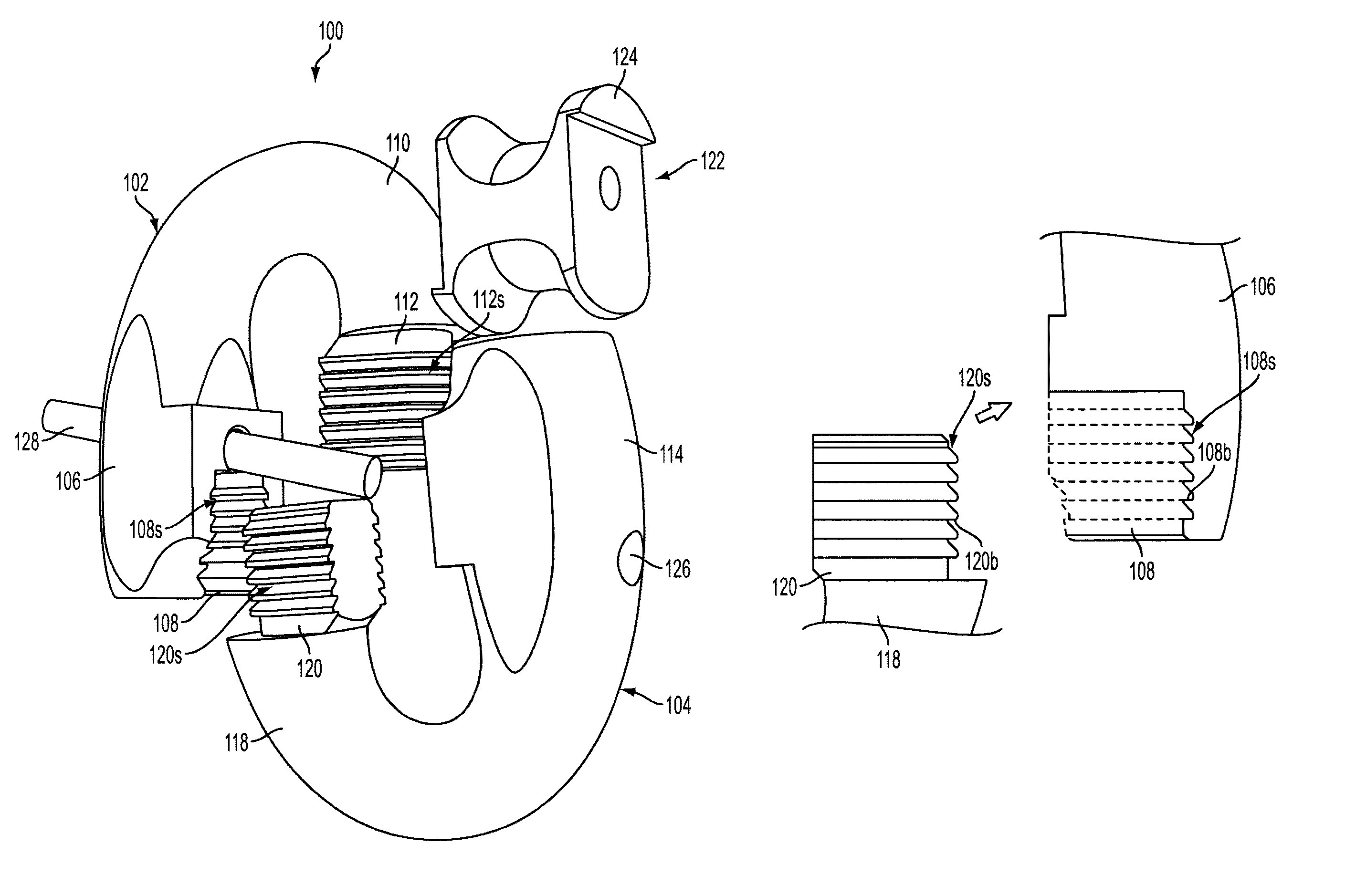
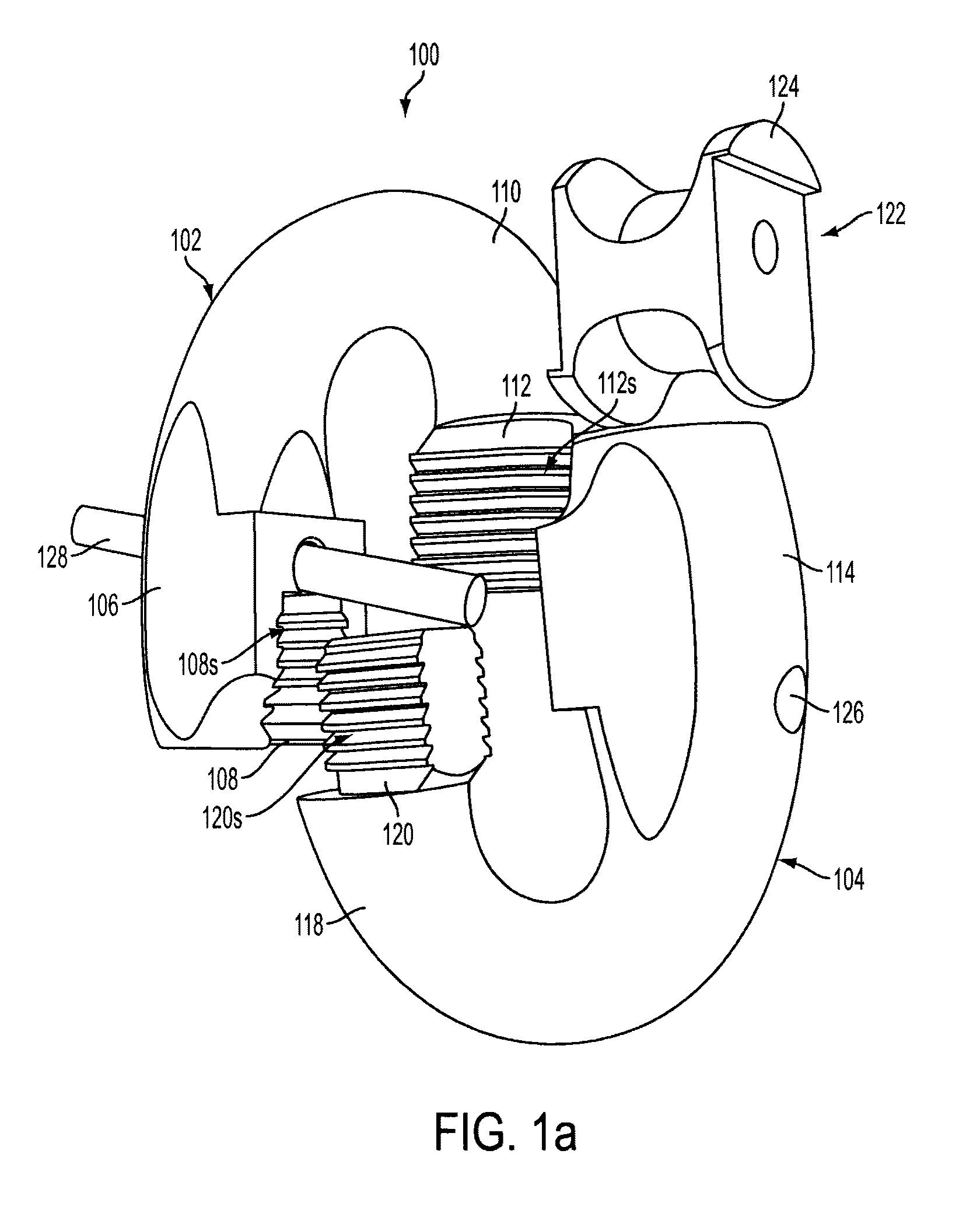
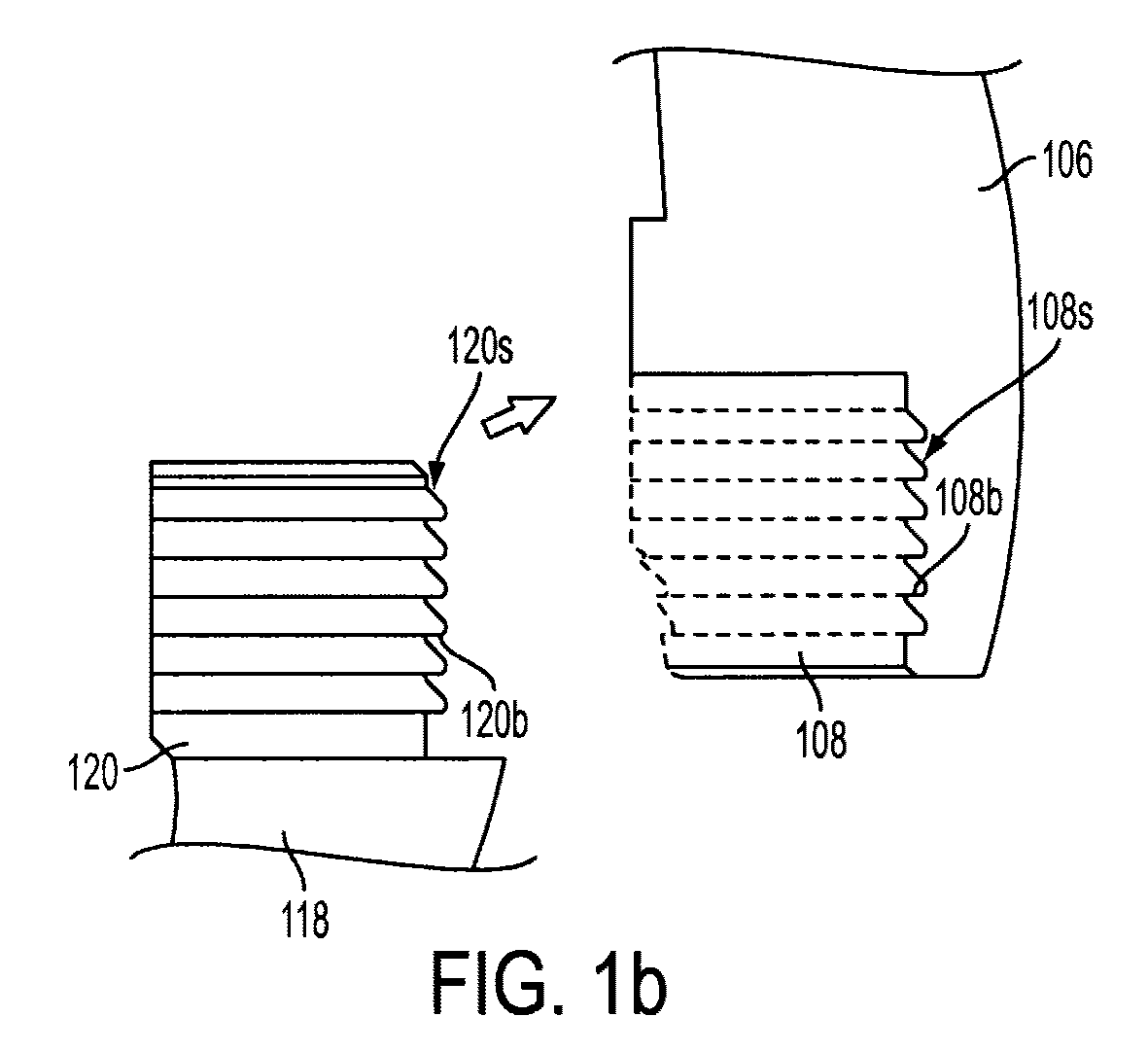
[0048]A break load test was conducted on a 76 mm / 3″ connector, wherein D=1.30 d, as shown in FIGS. 1-3. FIG. 6 is a graph showing the break load test results. Although only a 16% improvement was expected, the break load test surprisingly yielded a break load of 8009.3 kN. In other words, the connector 100 of the present invention yielded a break load that was surprisingly 33% better than the connectors of the prior art. Moreover, the break load test also showed that the connector 100 failed in the crown area, rather than at the locking mechanism. Traditionally, such connectors fail at the locking mechanism. In this test, however, the locking mechanism remained intact and in fact, even after the connector of the present invention failed, the locking mechanism remained intact and was easily disassembled.


PUM

PropertyMeasurementUnit
diameteraaaaaaaaaa
thicknessaaaaaaaaaa
shapeaaaaaaaaaa

Abstract

This invention relates to a connector, particularly to a shackle suitable for use in connecting two links of a chain or a chain to an anchor, more particularly to a connector comprising a first portion and a second portion, at least one first connector arm on the first portion and at least one second connector arm on the second portion, wherein both the first and second connector arms have multiple bearing surfaces, preferably six, and are able to engage one another when the connector is coupled by means of the bearing surfaces. The connector of the present invention has the advantage of having a break load of 1.3[0.0274 d2(44−0.08 d) kN, wherein d is the nominal diameter, and preferably a thickness of 1.3 d.

Description

FIELD OF INVENTION[0001]The present invention relates to a connector, particularly to a joining link or shackle suitable for use in connecting chains or a chain and an anchor.BACKGROUND OF INVENTION[0002]Anchor chains for marine use can be connected using known designs of shackles. Shackles usually comprises at least two portions, each of which will usually connect with a respective link on separate chains or with a link on a chain and an anchor, before the two shackle portions are connected together to join the chains or the chain to the anchor. The shackle should preferably be capable of withstanding the same forces as the chain links, but this is often a difficult compromise for the multipart shackle and frequent inspections are needed to assess the condition of the shackles, which is costly and inconvenient.[0003]There are many different styles of shackles, swivels and connecting links. The two main types of connecting links (chain or anchor) in use are Kenter style links or “Ba...

Claims


Application Information

Patent Timeline
Patent Type & Authority Patents(United States)
IPC IPC(8): B21L13/00F16G15/02
CPCF16G15/04F16G15/02F16G13/14
Inventor FEUERSTEIN, OLIVER
Owner SCHMIEDESTUCK VERTRIEB FEUERSTEIN
Why Eureka
Try Eureka