Plasma display panel drive method of determining a subfield, having a low luminance, for performing an every-cell initialization operation and setting a width of a sustain pulse of the subfield for performing the every-cell initialization operation

subfield technology, applied in the field of driving a plasma display panel, can solve the problems of weak discharge, easy increase of discharge delay, weak wall charge stored on the electrode, etc., and achieve the effect of suppressing the intensity of erroneous discharge and good display quality

Active Publication Date: 2012-01-03
PANASONIC CORP
View PDF25 Cites 1 Cited by
  • Summary
  • Abstract
  • Description
  • Claims
  • Application Information

AI Technical Summary

Benefits of technology

[0017]The present invention is proposed to solve such problems, and an object thereof is to provide a plasma display panel driving method that can achieve image display with good quality by suppressing the intensity of erroneous discharge.
[0019]According to the present invention, the intensity of the erroneous discharge can be suppressed to derive the good display quality. Moreover, by increasing the width of the first sustain pulse, the second sustain pulse used to have a difficulty in performing discharge can perform discharge with stability.

Problems solved by technology

This causes weak discharge in every discharge cell, and weakens the wall charge stored on the electrodes.
However, because the data electrodes are each coated thereon with a fluorescent element whose secondary electron emission coefficient is low, the discharge delay is easily increased for the initial discharge with the data electrodes each serving as a cathode.
However, increasing the partial pressure of xenon, as such, results in a tendency of increasing the discharge delay of the initial discharge.
Moreover, if the panel is used for a long length of time, the discharge delay is increased for the discharge cells.
If the discharge delay is increased for the discharge cells as such, the initial discharge becomes unstable, and in the discharge cells with the longer discharge delay, the initial discharge that is supposed to be less intense in the ascending lamp period is sometimes increased in intensity.
Also with the longer discharge delay, the writing discharge to be caused only to the display cells in a writing period is made unstable.
The wall charge is thus not sufficiently formed, and there may be a case of failing in sustain discharge in the subsequent sustain period.
That is, the discharge cells other than the display cells are illuminated, thereby resulting in erroneous discharge.
Furthermore, because the intensity of such erroneous discharge is increased with a larger number of sustain pulses, the erroneous discharge is considerably conspicuous in the SFs with the larger luminance weight.
As such, the erroneous discharge occurring in the conventional drive method is very conspicuous, thereby greatly degrading the display quality.

Method used


Image

  • Plasma display panel drive method of determining a subfield, having a low luminance, for performing an every-cell initialization operation and setting a width of a sustain pulse of the subfield for performing the every-cell initialization operation
  • Plasma display panel drive method of determining a subfield, having a low luminance, for performing an every-cell initialization operation and setting a width of a sustain pulse of the subfield for performing the every-cell initialization operation
  • Plasma display panel drive method of determining a subfield, having a low luminance, for performing an every-cell initialization operation and setting a width of a sustain pulse of the subfield for performing the every-cell initialization operation

Examples


first embodiment

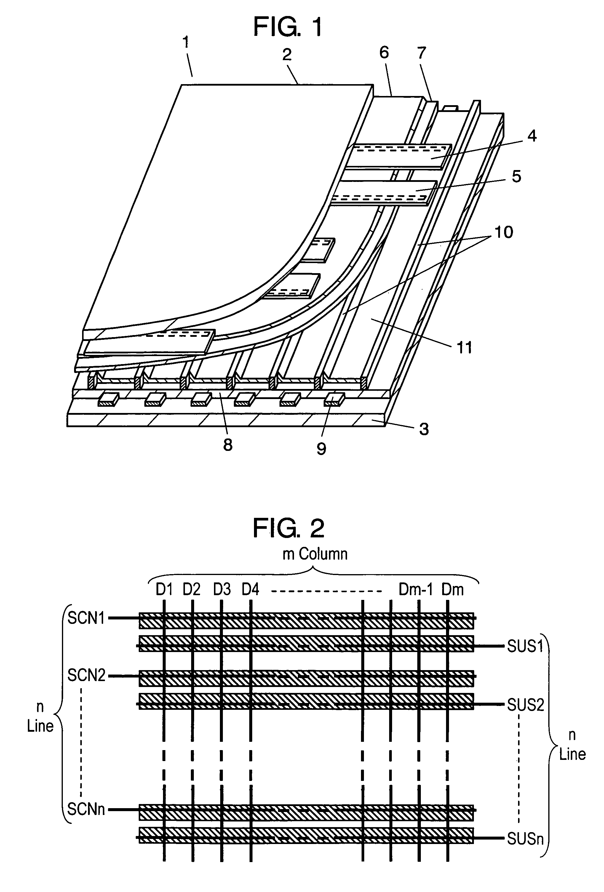
[0032]FIG. 1 is a perspective view of main portions of a panel for use in a first embodiment of the present invention. Panel 1 has such a configuration that glass-made front and rear substrates 2 and 3 are disposed opposing each other, and a discharge space is formed therebetween. Front substrate 2 is formed thereon with scanning electrode 4 and sustain electrode 5 configuring display electrodes, which are disposed in parallel for use as a pair, and such a pair is plurally formed. Dielectric layer 6 is formed to cover scanning electrodes 4 and sustain electrodes 5, and on dielectric layer 6, protection layer 7 is formed. In order to cause discharge with stability, protection layer 7 is preferably made of a material whose secondary electron emission coefficient is high and the sputtering resistance is high, and actually used is a thin film made of magnesium oxide (MgO). Rear substrate 3 is provided thereon with a plurality of data electrodes 9 covered by insulator layer 8, and on ins...

second embodiment

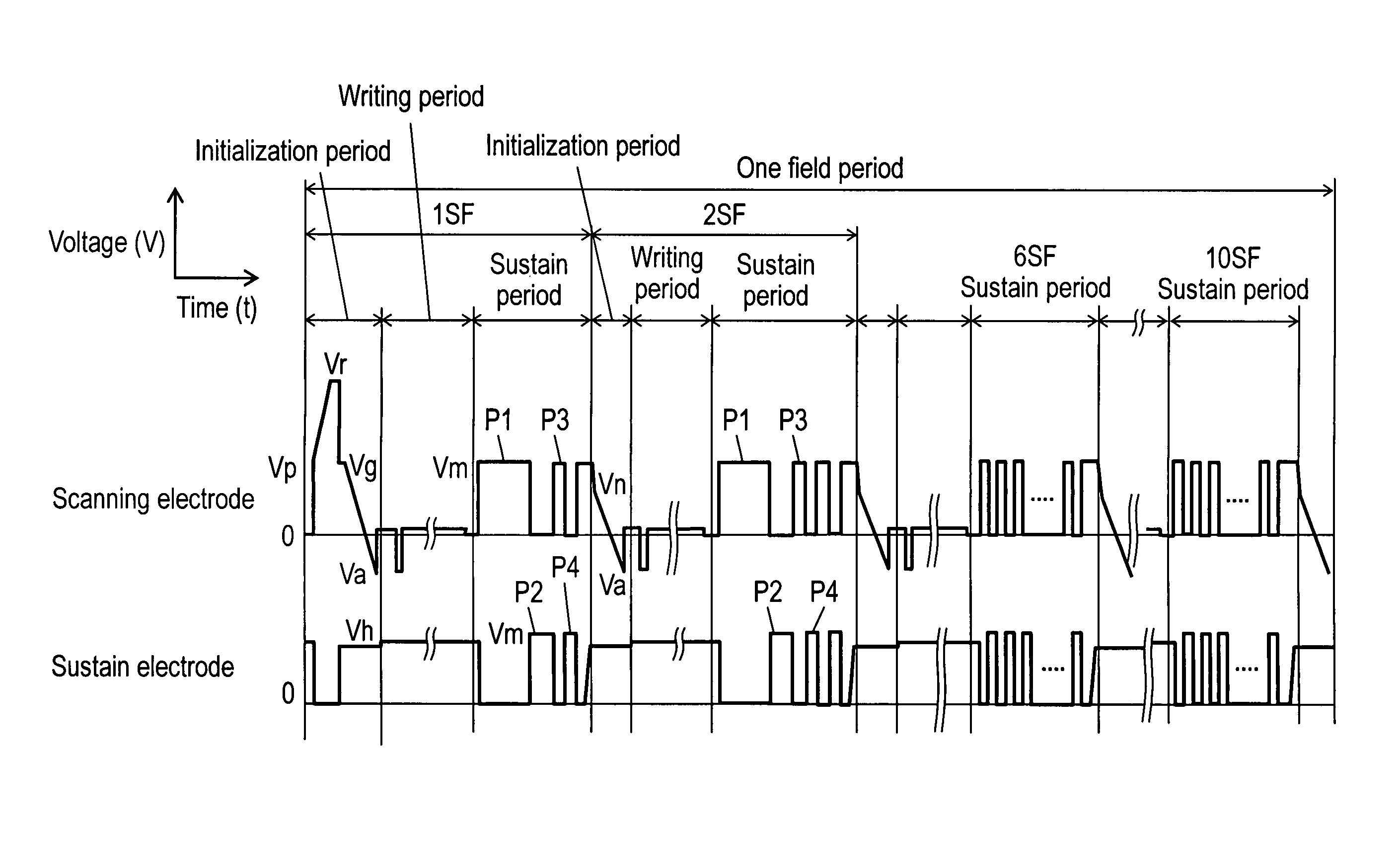
[0053]Described next is a second embodiment of the present invention. FIG. 6 is a diagram showing a drive waveform for application to the scanning electrodes and the sustain electrodes of panel 1 in the second embodiment of the present invention. A field period of FIG. 6 is configured by 11 subfields, i.e., 10 subfields same as those in the drive waveform of FIG. 4 plus a subfield having the smaller luminance weight than the 1SF of FIG. 4. That is, the 2SF to 11SF of FIG. 6 are each have a luminance weight same as that of the 1SF to 10SF of FIG. 4, and the 1SF of FIG. 6 is the additional subfield. For example, the subfields of the 1SF to 11SF have the luminance weights of (0.5, 1, 2, 3, 6, 11, 18, 30, 44, 60, and 80), respectively. The subfields each include an initialization period, a writing period, and a sustain period, and the operation in the respective periods is similar to that of the first embodiment. The 3SF to 11SF of FIG. 6 have the same waveform as the 2SF to 10SF of FIG...

third embodiment

[0057]Described next is a third embodiment of the present invention. FIG. 7 is a diagram showing a drive waveform for application to the scanning electrodes and the sustain electrodes of panel 1 in the third embodiment of the present invention. Similarly to the drive waveform of FIG. 4, a field period includes 10 subfields, and each of the subfields includes an initialization period, a writing period, and a sustain period. The operation in the respective periods is similar to that of the first embodiment.

[0058]In the third embodiment, as shown in FIG. 7, out of the subfields configuring a field period, a plurality of subfields are in charge of the every-cell initialization operation, and these subfields in charge of the every-cell initialization operation are those with low-luminance. That is, the every-cell initialization operation is performed in the initialization period of the 1SF and 3SF, and the selective initialization operation is performed in the initialization period of th...


PUM


Abstract

A plurality of subfields of a field period includes a subfield for performing an every-cell initialization causing an initial discharge in every discharge cell in an initialization period, and includes a subfield for performing a selective initialization causing the initial discharge in a predetermined discharge cell in the initialization period. In a low-luminance subfield, the every-cell initialization is performed, and a low-luminance subfield is subsequently located (in the field period) to the subfield for the every-cell initialization. In a sustain period of the subfield for performing the every-cell initialization or a sustain period of the low-luminance subfield, a width of a first sustain pulse is set wider than a width of a second sustain pulse, and the width of the second sustain pulse is set wider than the width of a third sustain pulse and subsequent others.

Description

[0001]This application is a U.S. National Phase Application of PCT International Application PCT / JP2006 / 303116.BACKGROUND OF THE INVENTION[0002]1. Field of Invention[0003]The present invention relates to a method of driving a plasma display panel for use as a low-profile and lightweight display device with a large screen.[0004]2. Description of the Related Art[0005]An alternating-plane discharge-type panel typified by a plasma display panel (hereinafter, simply referred to as “panel”) is formed with a large number of discharge cells between a front plate and a rear plate, which are disposed opposing each other. The front plate is formed with, on a front glass substrate, a plurality of display electrodes configuring a plurality of pairs of scanning electrode and sustain electrode in a parallel manner, and to cover such display electrodes, a dielectric layer and a protection layer are formed. The rear plate is formed with a plurality of parallel data electrodes on a rear glass substra...

Claims


Application Information

Patent Timeline
Patent Type & Authority Patents(United States)
IPC IPC(8): G09G3/28G09G3/288G09G3/20G09G3/291G09G3/294G09G3/298H04N5/66
CPCG09G3/2022G09G3/2927G09G3/2946G09G2310/066G09G2320/041G09G3/292
Inventor OGAWA, KENJIMURAKOSO, TOMOHIROTSUJITA, YOSHIKISASAKI, KENJIKOSHIO, YOHEI
Owner PANASONIC CORP
Why Eureka
Try Eureka