Method and apparatus for coupling and uncoupling an injection valve pin

a technology of injection valve pins and coupling devices, which is applied in the field of coupling assemblies, can solve problems such as pin misalignment, bent or even broken, and achieve the effects of preventing pins from being twisted, bent or broken

Active Publication Date: 2012-01-10
SYNVENTIVE MOLDING SOLUTIONS INC
View PDF67 Cites 93 Cited by
  • Summary
  • Abstract
  • Description
  • Claims
  • Application Information

AI Technical Summary

Problems solved by technology

These temperature differences and / or differences in thermal expansion (during heating / cooling) of the various parts can place undesirable side load forces on the pin, causing the pin to become misaligned, bent or even broken.
Still further, the pin may transmit heat from a hot part to a cold part of the machine, which again would be undesirable.

Method used


Image

  • Method and apparatus for coupling and uncoupling an injection valve pin
  • Method and apparatus for coupling and uncoupling an injection valve pin
  • Method and apparatus for coupling and uncoupling an injection valve pin

Examples


Embodiment Construction

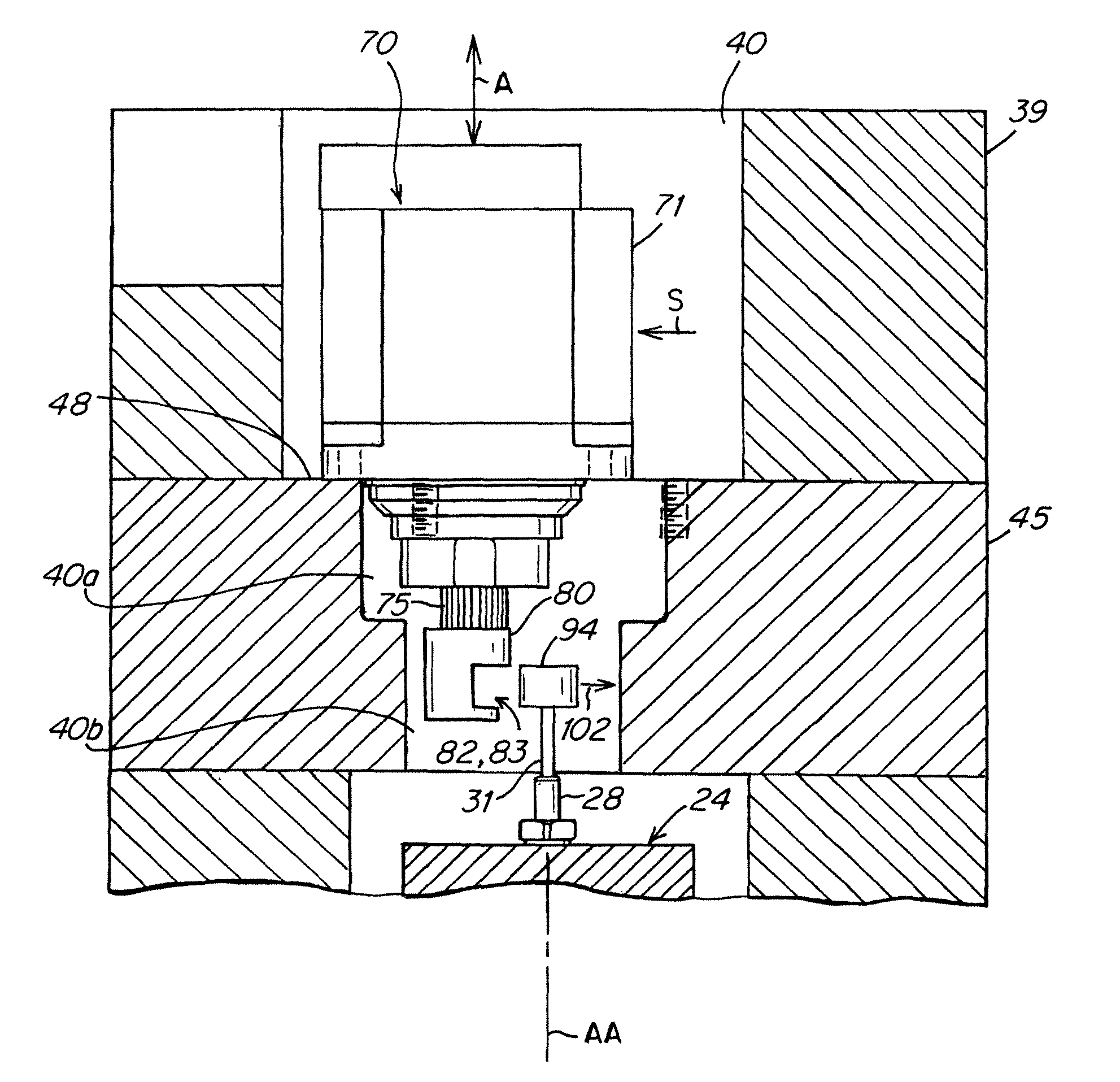
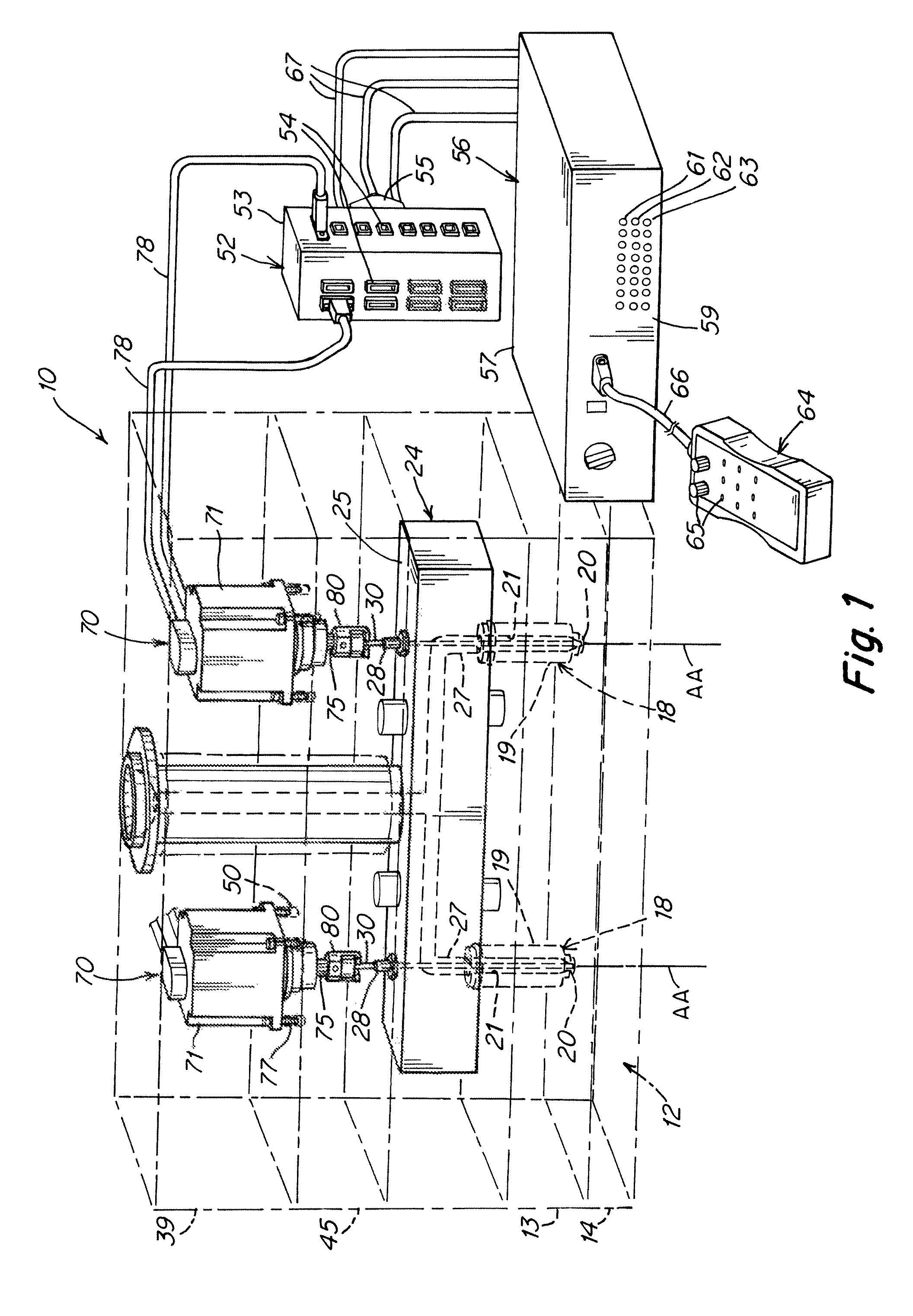
[0082]FIG. 1 is an overview of a coupling apparatus mounted in an injection molding apparatus according to one embodiment of the present invention. The coupling apparatus enables radial engagement and disengagement of an actuator and a valve pin assembly such that the valve pin assembly can remain extended into the manifold while the actuator either alone or together with the mounting plate, is / are removed.

[0083]An injection molding apparatus 10 includes a series of layered components forming a stack. Here the component layers of the stack are shown vertically arranged, one on top of another, although in use the entire stack would typically be rotated 90°. For ease of description, the stack will be described as a vertical stack even through in use it is not so disposed. At one end of the stack, here referred to as the bottom end of the stack, a mold 12 has a cavity (not shown) for receiving hot molten plastic fed through a gate 20 of an injection nozzle 18. The nozzle 18 is mounted ...


PUM

PropertyMeasurementUnit
radial distanceaaaaaaaaaa
radial movementaaaaaaaaaa
distanceaaaaaaaaaa

Abstract

An injection molding system comprising an actuator, a mounting plate, a mold and a manifold mounted between the mounting plate and the mold, the mounting plate being removably coupled to the mold, the actuator comprising an actuating member reciprocally drivable along an axial path of travel and a housing removably coupled to the mounting plate; a valve pin coupled to the shaft of the actuator for movement of the valve pin together with movement of the actuating member, the valve pin comprising a pin stem and a pin connector; the actuator having an actuator coupling adapted to reversibly couple to and decouple from the pin connector in a radial direction relative to the axial path of travel, the pin stem extending from the actuator into the manifold when the housing of the actuator is coupled to the mounting plate and the pin connector is received within the actuator coupling; the actuator housing being mounted on or within the mounting plate for radial movement upon decoupling of the actuator housing from the mounting plate such that the pin connector is decouplable from the actuator coupling upon said radial movement while the actuator housing is disposed on or within the mounting plate, the actuator being removable from on or within the mounting plate leaving the valve stem behind extending into the manifold.

Description

[0001]This is a CIP of Ser. No. 12 / 436,458 filed May 6, 2009 now abandoned.FIELD OF THE INVENTION[0002]This invention relates to a coupling assembly that provides one or more of mechanical and thermal isolation between a pin and an actuator for moving the pin. In a particular embodiment an apparatus and method are disclosed for coupling and decoupling of a valve pin assembly to an actuator in an injection molding apparatus.BACKGROUND[0003]There are various industrial applications in which an elongated shaft, also referred to as a pin, must be driven translationally, i.e., in the direction of the elongated (longitudinal) axis of the pin. Typically, the pin has a pin head at one end for engagement by the drive actuator assembly. In various applications, it may be desirable or necessary to mechanically or thermally isolate, in at least some respect, the pin from the actuator assembly.[0004]For example, in hot runner systems used in injection molding, valve pins are used to open and clo...

Claims


Application Information

Patent Timeline
Patent Type & Authority Patents(United States)
IPC IPC(8): B29C45/23
CPCB29C45/1775B29C45/2806Y10T29/49815B29C2045/2824Y10T29/49826B29C2045/1792
Inventor GALATI, VITOSAVOIE, PAUL JOSEPHBERNIER, ALBERT R.
Owner SYNVENTIVE MOLDING SOLUTIONS INC
Why Eureka
Try Eureka