Portable electronic device with micro-projecting module

a technology of electronic devices and modules, applied in the field of portable electronic devices, can solve the problems of difficult to find heightening articles with appropriate height in emergency and practical use, and the way to insert heightening articles under the lens parts is very inconvenient, so as to avoid affecting the brightness and lifespan of leds, the effect of discharging hea

Inactive Publication Date: 2012-01-10
CHUANG YI FANG
View PDF11 Cites 3 Cited by
  • Summary
  • Abstract
  • Description
  • Claims
  • Application Information

AI Technical Summary

Benefits of technology

[0011]By arranging a heat-conducting plate between the micro-projecting module and the bottom through hole, the invention can dissipate the heat generated from the LEDs of the micro-projecting module to the ambience. In the invention, the heat-conducting plate may make a heat exchange with the ambience through the bottom through hole, avoid influencing the brightness and lifespan of the LEDs. Furthermore, when the supporting stand is rotated to a developing position, the lens can be hold up from the placing surface during using period, so the portable electronic device with micro-projecting module is shown as an inclined configuration with an increase of projecting angle, making the light beam of the image clearly and entirely projected out without any hindrance.

Problems solved by technology

Following a gradual maturity of LED technology and a gradual micronization of micro-projecting module, it gradually becomes undifficult to adopt LEDs as a light source of the micro-projecting module integrated with a portable electronic device.
However, during the meantime when the brightness of the light beam is notably increased, the micro-projecting module also faces a heating problem arisen from the LEDs, so an appropriate heat-dissipating device has to be designed to effectively expel the heat generated from the LEDs.
However, the way to insert a heightening article under the lens part is very inconvenient.
Besides, it is sometimes very difficult to find a heightening article with appropriate height in time of emergency and in terms of practical use.

Method used


Image

  • Portable electronic device with micro-projecting module
  • Portable electronic device with micro-projecting module
  • Portable electronic device with micro-projecting module

Examples


Embodiment Construction

[0016]In cooperation with attached drawings, the technical contents and detailed description of the present invention are described thereinafter according to a preferable embodiment, not used to limit its executing scope. Any equivalent variation and modification made according to appended claims is all covered by the claims claimed by the present invention.

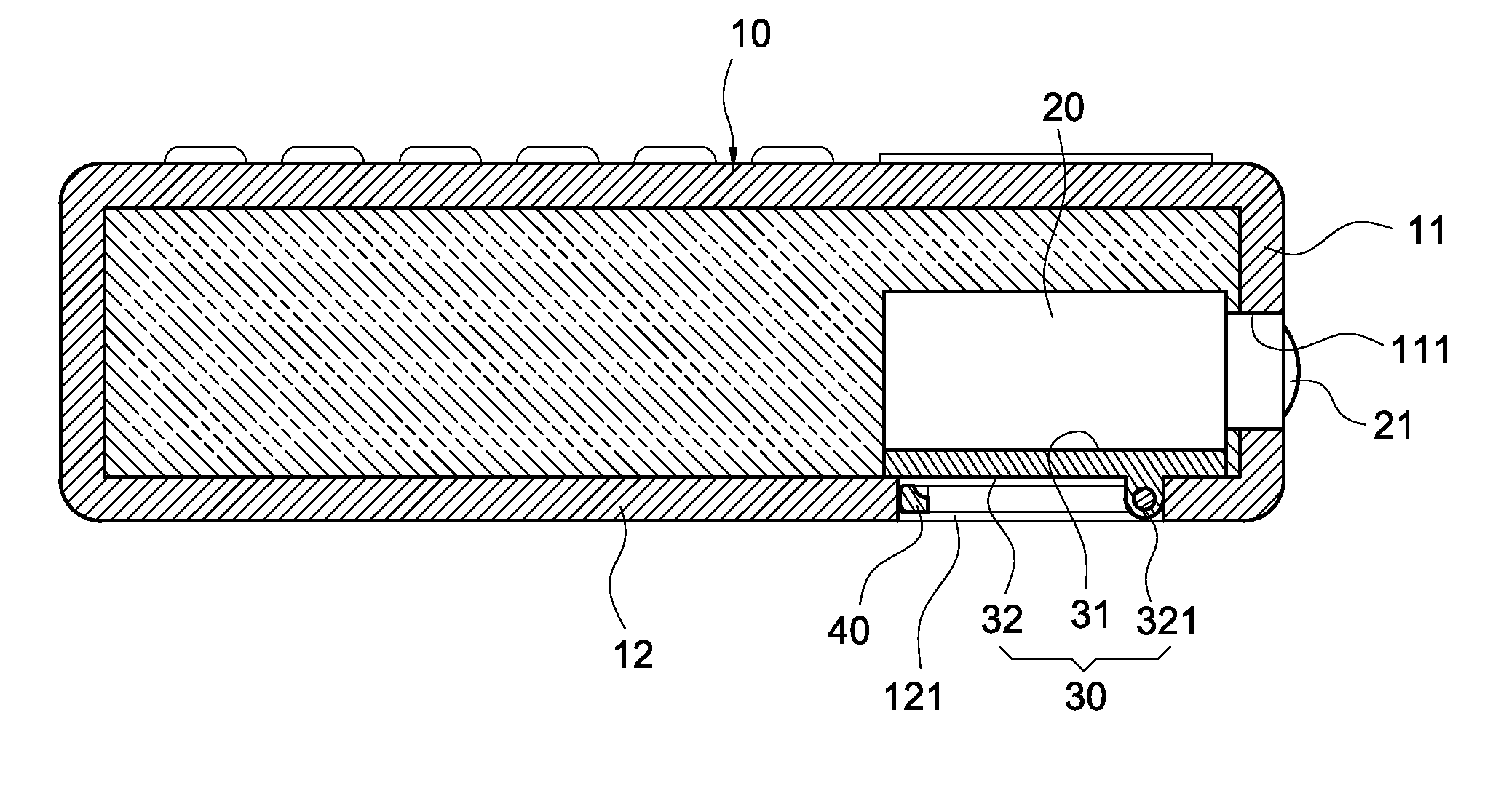
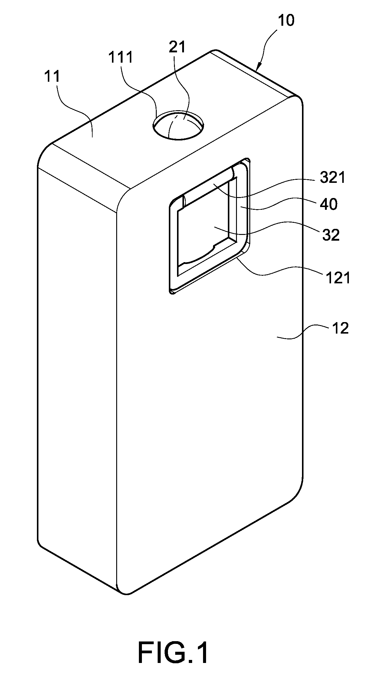
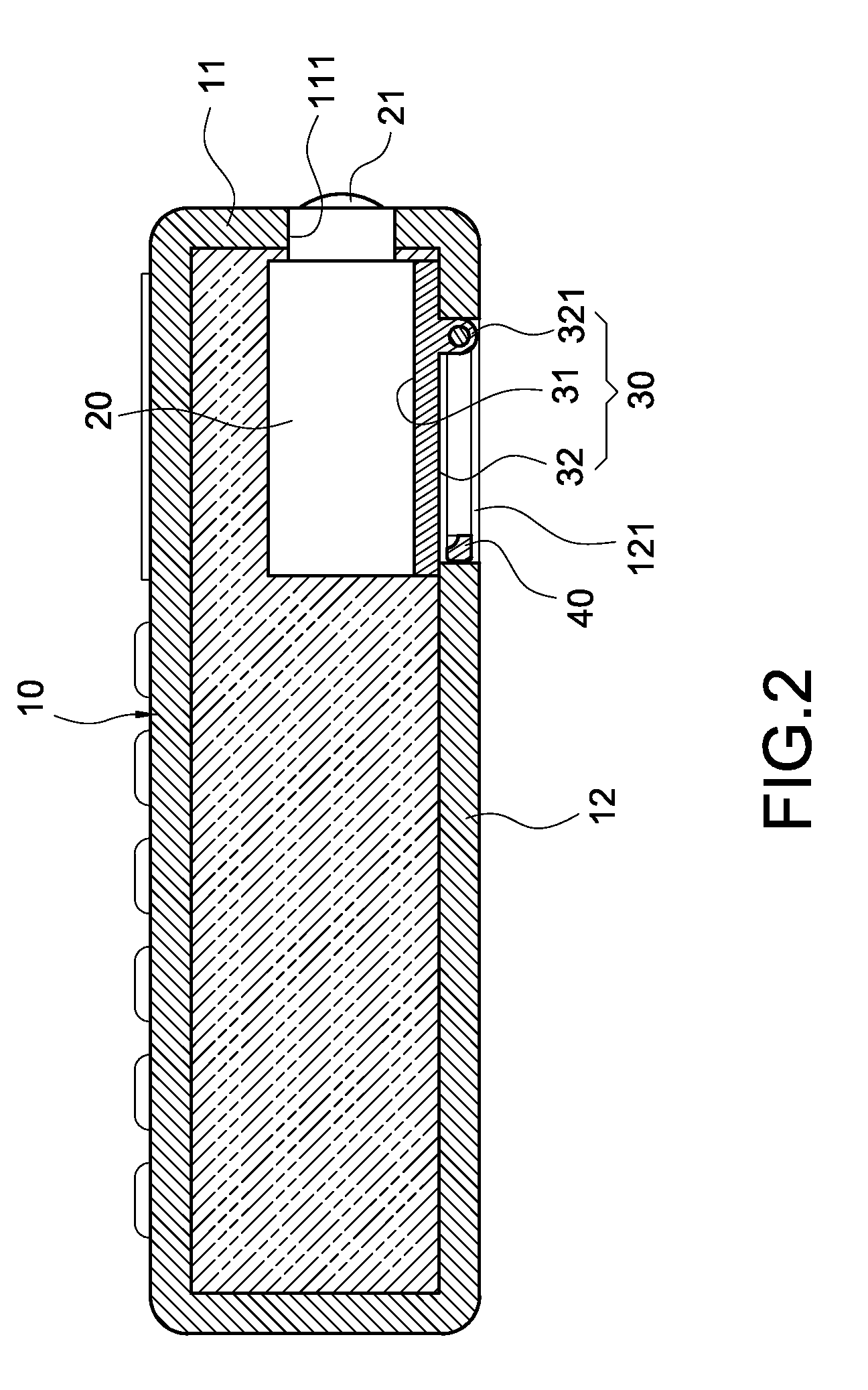
[0017]Please refer to FIG. 1 and FIG. 2, showing a portable electronic device with micro-projecting module according to a preferable embodiment of the present invention, including a shell body 10, a micro-projecting module 20, a heat-conducting plate 30 and a supporting plate 40.

[0018]The shell body 10 substantially shown as a cuboid has a front lateral plate 11 and a bottom lateral plate 12 substantially vertical to the front lateral plate 11. The front lateral plate 11 has a front through hole 111, while the bottom lateral plate 12 has a bottom through hole 121. In so doing, the bottom through hole 121 is positioned at one side...


PUM


Abstract

A portable electronic device with micro-projecting module includes a shell body, a micro-projecting module, a heat-conducting plate and a supporting stand. The shell body has a front lateral plate and a bottom lateral plate adjoining the front lateral plate. The front lateral plate has a front through hole, while the bottom lateral plate has a bottom through hole. The micro-projecting module is arranged in the shell body and has a lens exposing to an outside of the shell body from the front through hole. The heat-conducting plate is arranged in the shell body and is positioned between the micro-projecting module and the bottom through hole. In the meantime, the heat-conducting plate has a heat-absorbing face contacting the micro-projecting module and a heat-dissipating face abutted against the bottom through hole. The supporting stand may be pivoted onto the heat-dissipating face with a closing position substantially parallel to the heat-dissipating face after a rotation and a developing position by rotating a predetermined angle with respect to the heat-dissipating face.

Description

BACKGROUND OF THE INVENTION[0001]1. Field of the Invention[0002]The present invention in general relates to a portable electronic device, in particular, to a portable electronic device with micro-projecting module taking LEDs as light source.[0003]2. Description of Prior Art[0004]Following a gradual maturity of LED technology and a gradual micronization of micro-projecting module, it gradually becomes undifficult to adopt LEDs as a light source of the micro-projecting module integrated with a portable electronic device.[0005]In order to project out an image clearly, LEDs with high power must be adopted in the aforementioned micro-projecting module to provide a light beam with sufficient brightness. However, during the meantime when the brightness of the light beam is notably increased, the micro-projecting module also faces a heating problem arisen from the LEDs, so an appropriate heat-dissipating device has to be designed to effectively expel the heat generated from the LEDs. Other...

Claims


Application Information

Patent Timeline
Patent Type & Authority Patents(United States)
IPC IPC(8): G03B21/16
CPCG03B21/16
Inventor CHUANG, YI-FANG
Owner CHUANG YI FANG
Why Eureka
Try Eureka