Catheter guiding flexible connector

a flexible connector and catheter technology, applied in the field of catheter guiding flexible connectors, can solve the problems of wasting the valuable time of respiratory therapists and nurses, affecting patient comfort, and prolonging the time required for the completion of the procedur

Active Publication Date: 2012-01-24
LAZARUS MEDICAL
View PDF9 Cites 31 Cited by
  • Summary
  • Abstract
  • Description
  • Claims
  • Application Information

AI Technical Summary

Benefits of technology

[0009]It is also preferred that the exit end of the connector have a bearing portion with an outer diameter substantially equal to the outer diameter of the cup. The bearing portion extends upstream from the upstream end of the gradual taper. A hard sleeve concentrically disposed about and spanning across the bearing portion and the cup creates a void between the sleeve and the connector, but the bearing portion and cup afford sufficient contact to enable manipulation of the exit end of the connector by manipulation of the hard sleeve. A radial expansion at the upstream end of the bearing portion and an annular rim on the downstream end of the cup cooperate to prevent longitudinal motion of the sleeve on the connector.

Problems solved by technology

These actions cause discomfort to the patient, lengthen the time required for completion of the procedure, waste the valuable time of respiratory therapists and nurses and expend possibly precious time for the patient undergoing the procedure.
More significantly, disconnection causes a loss of ventilator pressure to the patient which can be rapidly physiologically catastrophic, cause a loss of sterility possibly resulting in more infections and further subject the patient to more stressful discomfort including the experience of a “smothering” feeling from no longer being on the ventilator.
A disconnect from the pressure of the ventilator circuit can result in rapid “flooding” of the alveoli with fluid, resulting in extremely quick decompensation, perhaps in as little as the time for eight breaths.
When the ventilator circuit is reconnected, it can take several hours for the regained pressure to clear the alveoli of fluid.
In this event, it is necessary to acquire from supply and install a different type of suction catheter which can be passed directly into the inner cannula entry, leaving the patient completely off the ventilator and increasing the time and expense of the procedure and the risks and discomfort to the patient.

Method used


Image

  • Catheter guiding flexible connector
  • Catheter guiding flexible connector
  • Catheter guiding flexible connector

Examples


Embodiment Construction

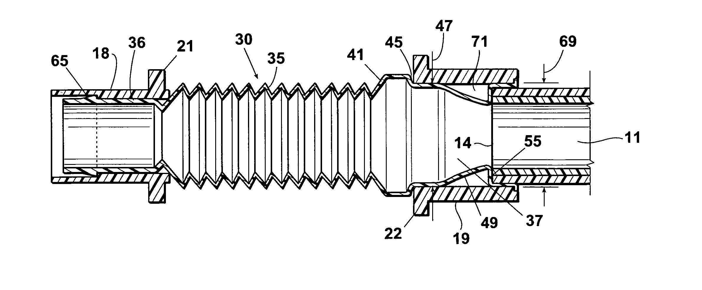
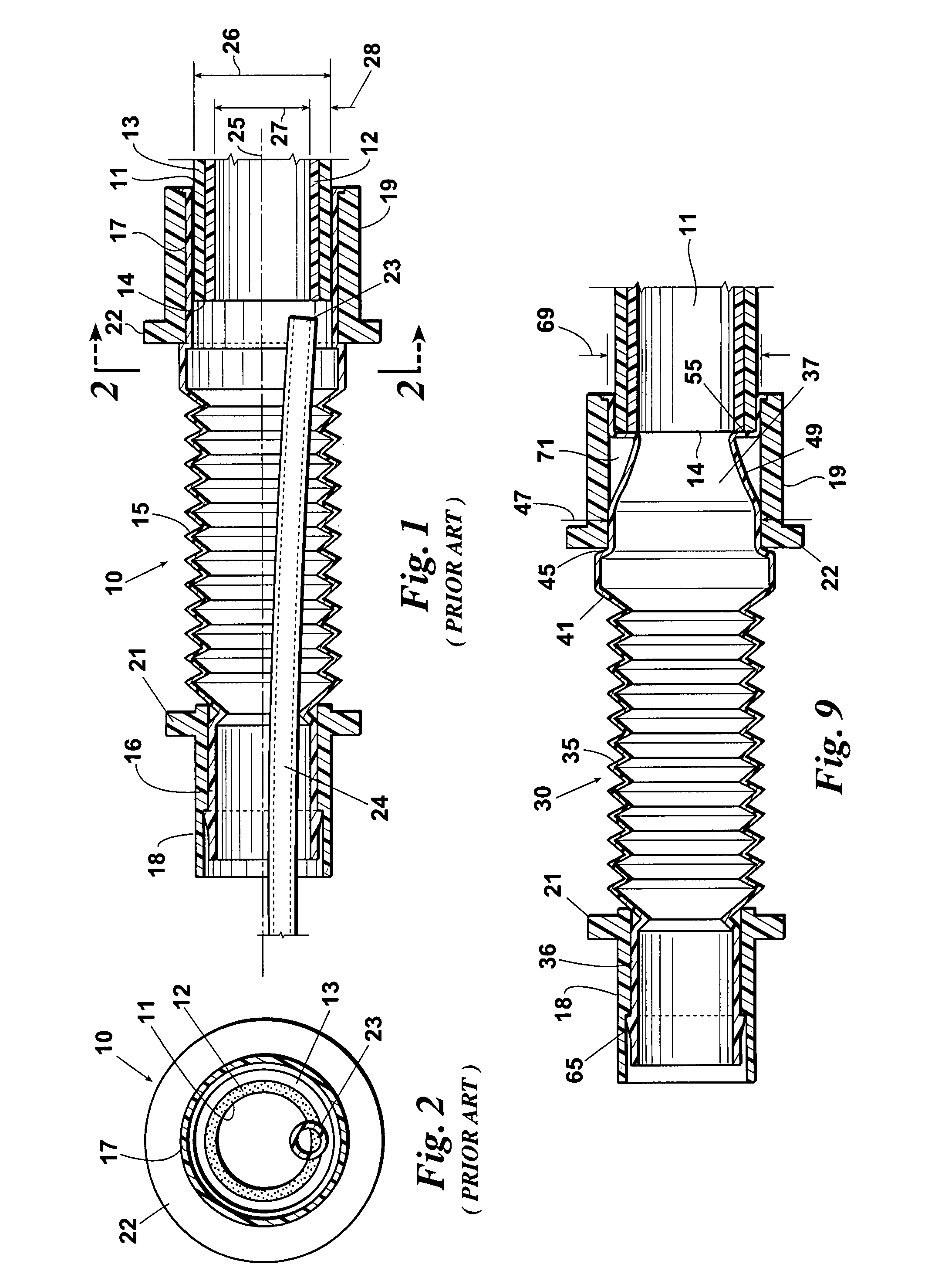
[0021]Turning first to FIGS. 1 and 2, a typical known flexible connector 10 is illustrated. The connector 10 is commonly used to couple the inlet end of a tracheotomy tube inner cannula 11 to the outlet port of an in-line catheter (not shown). The cannula 11 has a soft inner liner 12 and a hard outer case 13 which terminate at a relatively thick inlet face 14. The connector 10 has an elongated, flexible, accordion-like tubular body 15. The catheter entry end 16 of the tubular body is adapted to be serially coupled in pneumatic communication with the catheter outlet port (not shown). The catheter exit end 17 of the tubular body 15 is adapted to be serially coupled in pneumatic communication with the inlet end of the tracheotomy tube inner cannula 11. The entry and exit ends 16 and 17 of the connector body 15 are fitted with hard sleeves 18 and 19 with outer annular flanges 21 and 22, respectively. The sleeves 18 and 19 and flanges 21 and 22 are helpful in manipulating the connector 1...


PUM


Abstract

A flexible connector couples the inlet end of a tracheotomy tube inner cannula to an outlet port of an in-line catheter. The catheter exit end of the connector is adapted to be serially coupled in pneumatic communication with the inlet end of the tracheotomy tube inner cannula and also to guide the downstream tip of the catheter into the inlet end of the inner cannula in response to pushing of the catheter upstream of the catheter outlet port. Thus, the in-line catheter can be inserted into the tracheotomy tube inner cannula with little likelihood of having to compress or “flip” the connector or disconnect the connector from the tracheotomy tube and the patient from the ventilator circuit.

Description

BACKGROUND OF THE INVENTION[0001]This invention relates generally to tracheotomy associated equipment and more particularly concerns flexible connectors for coupling in-line catheters to tracheotomy tube inner cannulas.[0002]In-line suction catheters are used to permit a patient to continuously respirate through a tracheotomy tube while the catheter is inserted into the inner cannula of the tracheotomy tube. The in-line catheter has a housing with two inlet ports and an outlet port. A ventilator circuit is connected to one of the housing inlet ports. The catheter extends into the housing through the other housing inlet port. A flexible connector couples the housing outlet port in serial communication with the inlet or ventilator end of the inner cannula. The air and catheter are pushed through the flexible connector into the inlet end of the cannula for administration to the patient. The flexible connector consists of an accordion-like tubular body with entry and exit collars on its...

Claims


Application Information

Patent Timeline
Patent Type & Authority Patents(United States)
IPC IPC(8): A62B9/04A62B9/06A61M16/00
CPCA61M16/0816A61M16/0875A61M16/0463A61M16/0465
Inventor WORLEY, BRIAN D.
Owner LAZARUS MEDICAL
Why Eureka
Try Eureka