Valved Fenestrated Tracheotomy Tube Having Inner and Outer Cannulae with Pressure Relief

a tracheotomy tube and valve technology, applied in the field of valved fenestrated tracheotomy tubes, can solve the problems of no known commercially available device, no better art than, and no widespread us

Inactive Publication Date: 2009-09-24
HANSA MEDICAL PROD
View PDF38 Cites 10 Cited by
  • Summary
  • Abstract
  • Description
  • Claims
  • Application Information

AI Technical Summary

Benefits of technology

[0011]According to another aspect of the invention, an outer cannula has a first port for orienting outside the neck of a wearer, a second port for orienting within the trachea of the wearer, a first passageway coupling the first port to the second port to permit the flow of gases from the first port to the second during inhalation by the wearer and from the second port during exhalation by the wearer, and a third port between the first and second ports. An inner cannula is provided for insertion into the first passageway via the first port when the wearer desires to be able to exhale through the wearer's pharynx. The inner cannula includes a fourth port for orienting adjacent the first port, a fifth port for orienting adjacent the second port and a second passageway coupling the fourth port to the fifth port to permit the flow of gases from the fourth port through the fifth during inhalation by the wearer and preventing the flow of gases from the fourth port during exhalation by the wearer. A first valve controls flow through the third port. The first valve assumes a first orientation to permit flow from the fourth port to the fifth port when the fourth port is at a higher pressure than the fifth port and a second orientation to prevent flow from the fourth port when the fifth port is at a higher pressure than the fourth port. A second valve assumes a first orientation when the flow of respiration products through the third port is relatively less impeded and a second orientation permitting respiration products to flow from the second port to the first port and out the first port when flow through the third port is relatively more impeded.

Problems solved by technology

There is no known commercially available device constructed as described in Hessler, et al.
Such talking tracheotomy tubes have been available for several years, but are not in widespread use, perhaps owing to numerous mechanical limitations.
No representation is intended by this listing that a thorough search of all material prior art has been conducted, or that no better art than that listed is available.

Method used


Image

  • Valved Fenestrated Tracheotomy Tube Having Inner and Outer Cannulae with Pressure Relief
  • Valved Fenestrated Tracheotomy Tube Having Inner and Outer Cannulae with Pressure Relief
  • Valved Fenestrated Tracheotomy Tube Having Inner and Outer Cannulae with Pressure Relief

Examples


Embodiment Construction

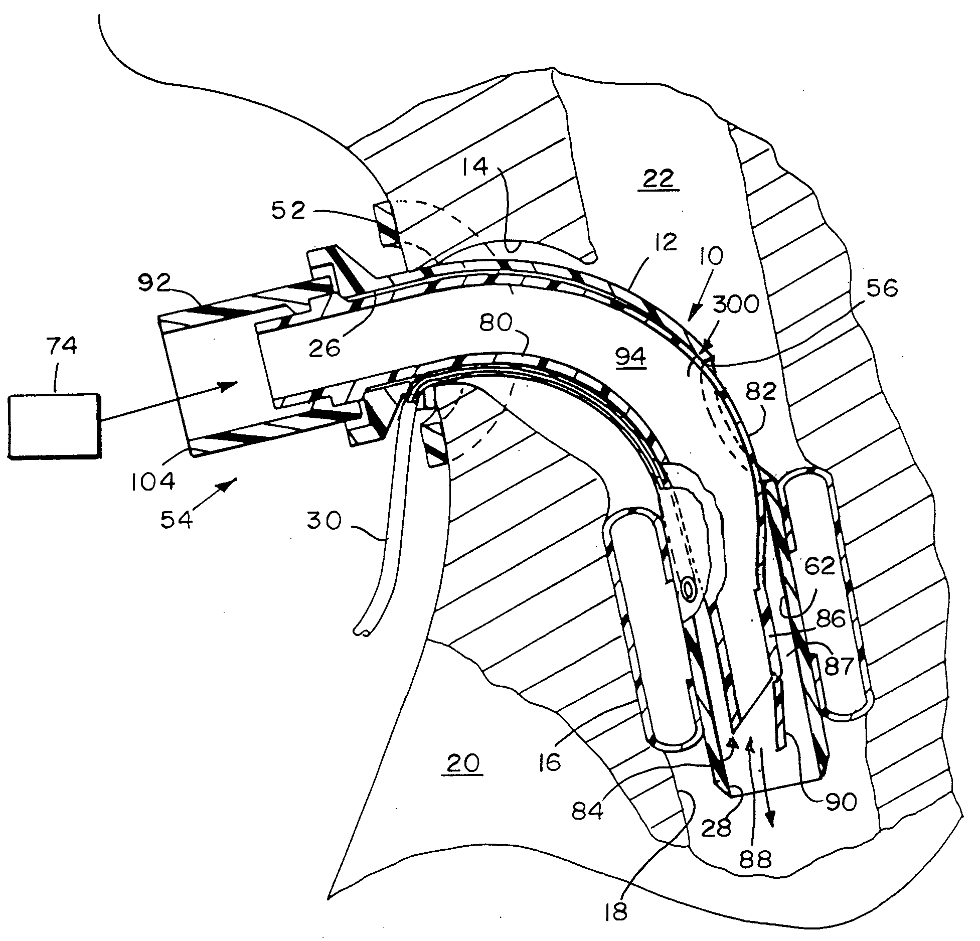
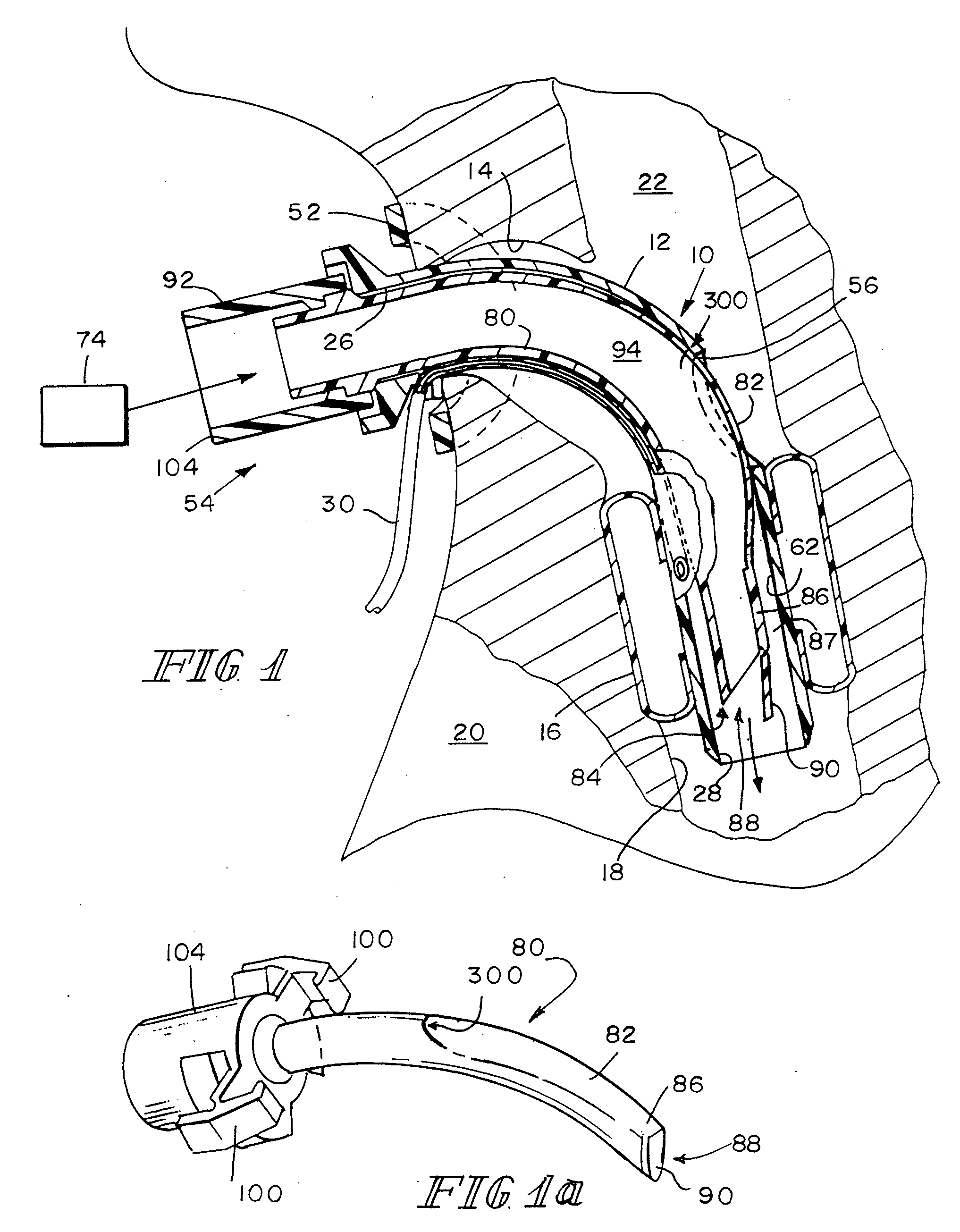
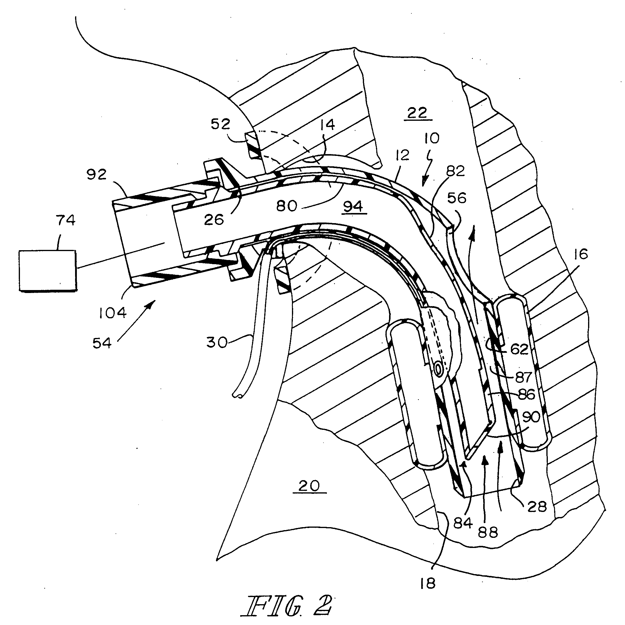
[0022]Referring now particularly to FIG. 1, a speaking tracheotomy tube system 10 includes an outer cannula 12 for insertion into a tracheostoma 14. Outer cannula 12 includes an inflatable cuff 16. Cuff 16 lies in the trachea 18 of a wearer 20 below the passageway 22 upward into the pharynx 24 of the wearer 20. Outer cannula 12 also includes a first port 26 which resides outside the neck of the wearer 20 during use and a second port 28 which resides inside the neck of the wearer 20 below cuff 16 during use. The cuff 16 is inflatable through a line 30 once the outer cannula 12 is in place in the trachea 18 to minimize the passage of secretions from the upper respiratory tract, including pharynx 24, downward into the lungs of the wearer 20. Such secretions pool above the cuff 16 when the cuff 16 is inflated in place, and may be evacuated as illustrated and described in U.S. Ser. No. 11 / 318,649.

[0023]The outer cannula 12 includes a pivotally mounted attachment plate 52 adjacent its pro...


PUM


Abstract

An outer cannula has a first port for orienting outside the neck of a wearer, a second port for orienting within the trachea of the wearer, a first passageway coupling the first port to the second port to permit the flow of gases from the first port to the second during inhalation by the wearer and from the second port during exhalation by the wearer, and a third port between the first and second ports. An inner cannula is provided for insertion into the first passageway via the first port when the wearer desires to be able to exhale through the wearer's pharynx. The inner cannula includes a fourth port for orienting adjacent the first port, a fifth port for orienting adjacent the second port and a second passageway coupling the fourth port to the fifth port to permit the flow of gases from the fourth port to the fifth during inhalation by the wearer. A first valve controls flow through the third port. A second valve assumes a first orientation when the flow of respiration products through the third port is relatively less impeded and a second orientation permitting respiration products to flow from the second port to the first port and out the first port when flow through the third port is relatively more impeded.

Description

CROSS-REFERENCE TO RELATED APPLICATIONS[0001]This is a related application to U.S. Ser. No. 11 / 318,649, filed Dec. 27, 2005 and published Jun. 28, 2007 as 2007 / 0144526. The disclosure of U.S. Ser. No. 11 / 318,649 is hereby incorporated herein by reference.FIELD OF THE INVENTION[0002]This invention relates to improvements in tracheotomy tubes.BACKGROUND OF THE INVENTION[0003]This invention is directed toward the problem of being unable to produce audible laryngeal voice, and thus, the inability to speak, that confronts individuals whose breathing is provided mechanically by a respirator which is connected to a cuffed tracheotomy tube inserted into the trachea of a wearer below the level of the vocal cords. The cuff on the tracheotomy tube is inflated, for example, with air, so that the cuff seals substantially fluid tight against the wall of the trachea. The purposes of the inflated cuff include: to protect against leakage of saliva and other secretions around the tracheotomy tube and...

Claims


Application Information

Patent Timeline
Patent Type & Authority Applications(United States)
IPC IPC(8): A61M16/20A62B9/02
CPCA61M16/0434A61M16/0427A61M16/0468A61M16/0465A61M16/0475
Inventor BLOM, ERIC D.
Owner HANSA MEDICAL PROD
Why Eureka
Try Eureka