Vacuum package system

a packaging system and vacuum technology, applied in the field of vacuum packaging systems, can solve the problems of high sterility of containers, low or non-pyrogenic level, low level of non-viable particulate matter, etc., and achieve the effect of reducing the number of contaminated containers

Active Publication Date: 2012-01-24
WEST PHARM SERVICES INC +1
View PDF55 Cites 138 Cited by
  • Summary
  • Abstract
  • Description
  • Claims
  • Application Information

AI Technical Summary

Problems solved by technology

However, the medical containers may be referred to as being sterile, pyrogen free and non-viable particulate matter free, meaning that the medical containers have a high sterility, a low or non-pyrogenic level and a low level of non-viable particulate matter.
However, polymeric or plastic vials and syringes are typically unable to withstand the temperature required to reduce pyrogens to a non-pyrogenic level and sterilize the vials and syringes.
The plastic vials and syringes may be washed and irradiated to reduce pyrogens and sterilize the vials and syringes, but the plastic vials and syringes are difficult to dry and the process is time consuming and generally will not result in removal of pyrogens to an acceptable level for filling.
Further, when medical containers are shipped in permeable boxes or trays in permeable bags, the vials and syringes may shift or vibrate during their shipment.
When the vials and syringes shift and / or vibrate during transport, they may rub against each other causing surface damage and potentially introducing particulates into the bag and onto the vials and syringes.

Method used


Image

  • Vacuum package system
  • Vacuum package system
  • Vacuum package system

Examples


second embodiment

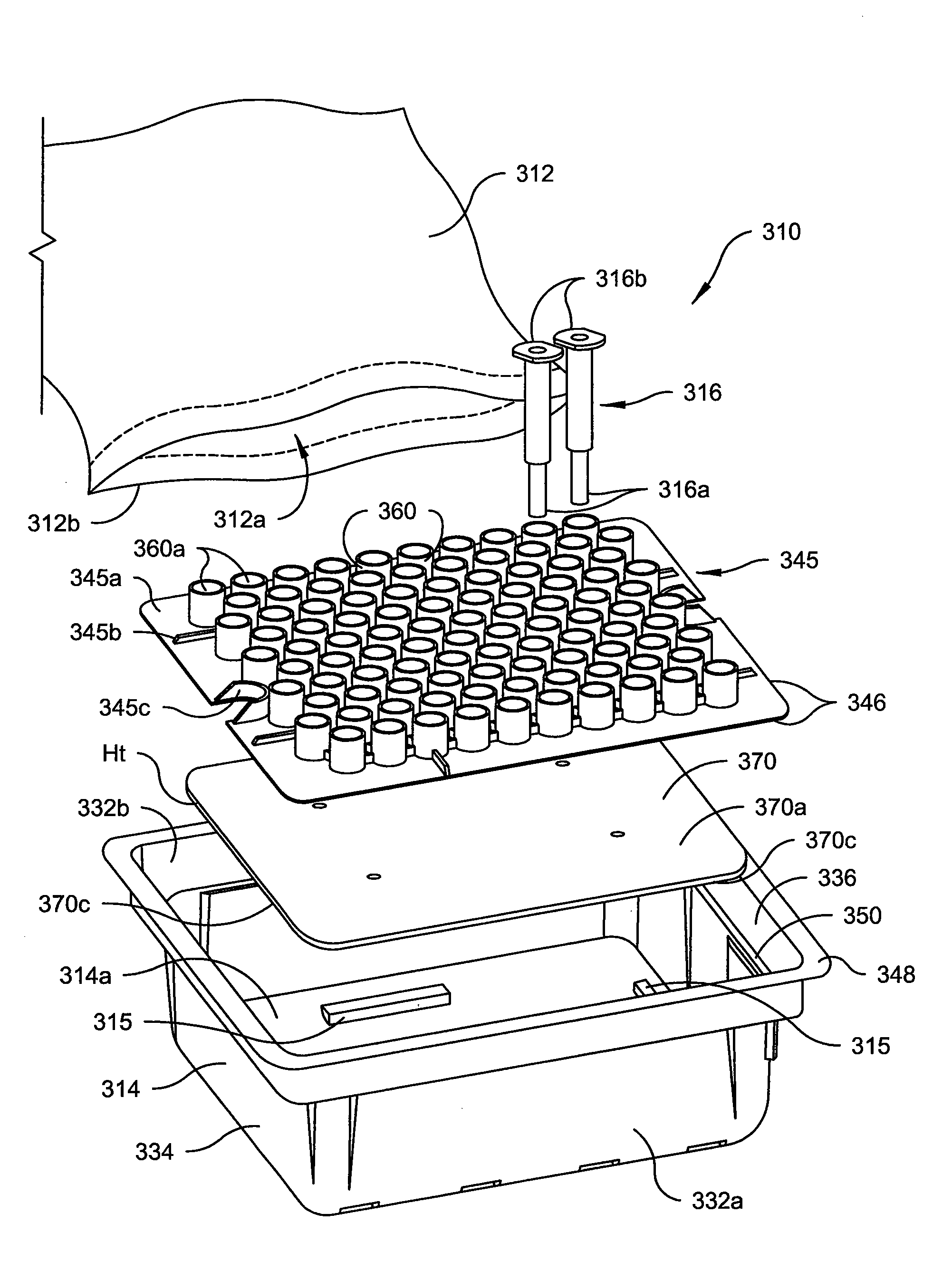
[0070]Referring to FIG. 9, a third preferred embodiment of the vacuum packaging system 310 is shown, including like reference numerals to indicate like elements throughout. The vacuum packaging system 310 of the third preferred embodiment is substantially similar in structure and operation to the second embodiment described above. In the third preferred embodiment, the vacuum packaging system 310 is used for transporting a plurality of medical containers that are preferably comprised of syringes 316. Each medical container 316 includes a head side 316a and a base side 316b, similar to that disclosed in the second preferred embodiment. A tray 314 receives and supports the medical container 316 within a nesting plate 345, as in the second preferred embodiment. The tray 314 includes opposing first and second sidewalls 332a, 332b, opposing front and rear walls 334, 336 and a bottom floor 314a. The walls 332a, 332b, 334, 336 extend generally vertically from the floor 314a of the tray 314...

third embodiment

[0074]Referring to FIGS. 10A-10B, a fourth preferred embodiment of the vacuum packaging system 410 is shown, including like referenced numerals to indicate like elements throughout. The vacuum packaging system 410 of the fourth preferred embodiment is substantially similar in structure and operation to the third embodiment described above, although certain structure is omitted from the drawings for clarify.

[0075]One primary difference between the fourth preferred embodiment and the third preferred embodiment is that the platform 470 of the fourth preferred embodiment includes a plurality of spaced-apart projections 472. Each projection 472 includes a side surface 472a that extends generally perpendicular to the floor 414a of the tray 414 and a top surface 474 that generally extends parallel to the floor 414a of the tray 414. Thus, a top surface of the platform 470 is perpendicularly spaced from the floor 414a by a predetermined distance. The predetermined distance is due to the heig...


PUM


Abstract

A vacuum packaging system for transporting a plurality of medical containers includes a plurality of medical containers each having a head side and a base side and a tray that receives and supports the medical containers. The tray includes opposing first and second sidewalls, opposing front and rear walls and a bottom floor. The walls extend generally vertically from the floor of the tray. At least one platform generally extends parallel to the floor of the tray. An air impervious flexible film defines an internal cavity. The air impervious flexible film completely surrounds the tray and the medical containers and the internal cavity is evacuated to and maintained at a predetermined vacuum level below atmospheric pressure. One of the head side and the base side of each medical container contacts a top surface of at least one platform when the medical containers are positioned in the tray.

Description

CROSS-REFERENCE TO RELATED APPLICATIONS[0001]This application is a continuation-in-part of pending U.S. patent application Ser. No. 11 / 171,814, filed Jun. 30, 2005 and entitled “Vacuum Packaging System and Method,” which claims the benefit of U.S. Provisional Application No. 60 / 584,826, filed Jul. 1, 2004.BACKGROUND OF THE INVENTION[0002]The present invention relates broadly to vacuum packaging systems and, more particularly, to a vacuum packing system that protects and preserves sterilized medical containers during storage and / or shipment.[0003]Medical containers generally must be sterile, have a low level of non-viable particulate matter and have a low or undetectable pyrogen level prior to the introduction of medication or another medical product into the medical container such that the product is not contaminated. One having ordinary skill in the art will realize that the medical containers are not necessarily completely sterile and free of all pyrogens prior to being filled wit...

Claims


Application Information

Patent Timeline
Patent Type & Authority Patents(United States)
IPC IPC(8): B65D25/10B65D81/20
CPCA61M5/002A61M5/008B65B5/067B65B31/06B65D25/108B65D81/203A61M2207/00A61M2209/06
Inventor VANDERBUSH, EDWARDYOUNG, SCOTTLUNDQUIST, JONYEAGER, RICKYTOGASHI, HIROSHI
Owner WEST PHARM SERVICES INC
Why Eureka
Try Eureka