Packing cartridges and pressure-dampening elements for plunger-type pumps

a technology of pressure-dampening elements and packing cartridges, which is applied in the direction of engine seals, borehole/well accessories, fluid removal, etc., can solve the problems of excessive wear, heat, and even breakage of the plunger, and achieve satisfactory seals for the piston or the plunger

Active Publication Date: 2012-01-24
CL PACKING SOLUTIONS
View PDF41 Cites 51 Cited by
  • Summary
  • Abstract
  • Description
  • Claims
  • Application Information

AI Technical Summary

Benefits of technology

[0054]According to a first aspect of the invention, a packing cartridge is provided for use in a packing bore of a plunger-type pump, wherein the packing bore has a generally cylindrical interior wall and a seat. The packing cartridge comprises, without limitation, a generally cylindrical sleeve further comprising an outer cylindrical profile adapted to be at least partially positioned in the packing bore, a first abutment ring positioned in the sleeve, and a second abutment ring positioned in the sleeve and co-axially spaced apart from the first abutment ring. Telescoping structures are operatively positioned between the first abutment ring and the second abutment ring to allow for squeezing of the first abutment ring and the second abutment ring co-axially closer to one another. A retaining ring is operatively positioned between the telescoping structures to retain the telescoping structures together.

Problems solved by technology

A major problem associated with positive-displacement fluid pumps, especially high-pressure pumps, is that of providing a satisfactory seal for the piston or plunger.
During the forward stroke of the plunger, the insertion of the plunger decreases the volume of the pumping chamber, which creates increasing fluid pressure in the chamber.
Over-tightening of the gland on the packing can cause excessive friction as the plunger reciprocates through the packing elements, causing excess wear, heat, and even breakage of the plunger.
As mentioned above, a major problem associated with positive-displacement fluid pumps, especially high-pressure pumps, is that of providing a satisfactory seal for the plunger.
Of course, the packing seals wear as the plunger reciprocates, and the fluid pumps require periodic maintenance to replace the worn seals.
The wear on the plunger packing is a particularly serious problem when the fluid being pumped contains suspended particles of silt, clay, sand, or other abrasive material.
The abrasive material tends to erode the packing causing early and frequent failure.
Packing failure is normally evidenced by the leakage of fluid past the packing.
This maintenance involves tedious and time-consuming operations, including removal of the packing gland, removal of the worn packing elements from the packing bore, re-assembly of new packing elements in the packing bore, and replacement and proper tightening of the gland.
Eventually, typically after about two-to-three years of pump operation, however, the packing bore itself will require a major overhaul.
During the reciprocating action of the plunger, the parts and pieces of the packing set have slight movement and this, along with corrosion, vibration and other factors, will cause the packing bore surface to deteriorate.
Further, as the packing wears and loosens, the packing will in turn will increasingly wear on the interior cylindrical wall of the plunger bore.
Eventually, the packing bore becomes useless as a sealing surface to prevent the compressed product from escaping from the pumping chamber to the pump exterior.
However, this alternative requires major overhaul of the pump.
However, this stuffing-box design is adapted for major overhaul of the fluid end and does not allow for the removal of the stuffing box without removing the fluid end from the power frame.
Such a separate stuffing box is massive and expensive because, in essence, it is a structural portion of the fluid end body.
Conventional plunger packings also present design problems in packing assemblies that require lubrication.
Over the years, many designs have been tried to reduce maintenance costs associated with such fluid pumps, however, problems with reliability and maintenance have continued to plague the pump technology.

Method used


Image

  • Packing cartridges and pressure-dampening elements for plunger-type pumps
  • Packing cartridges and pressure-dampening elements for plunger-type pumps
  • Packing cartridges and pressure-dampening elements for plunger-type pumps

Examples


Embodiment Construction

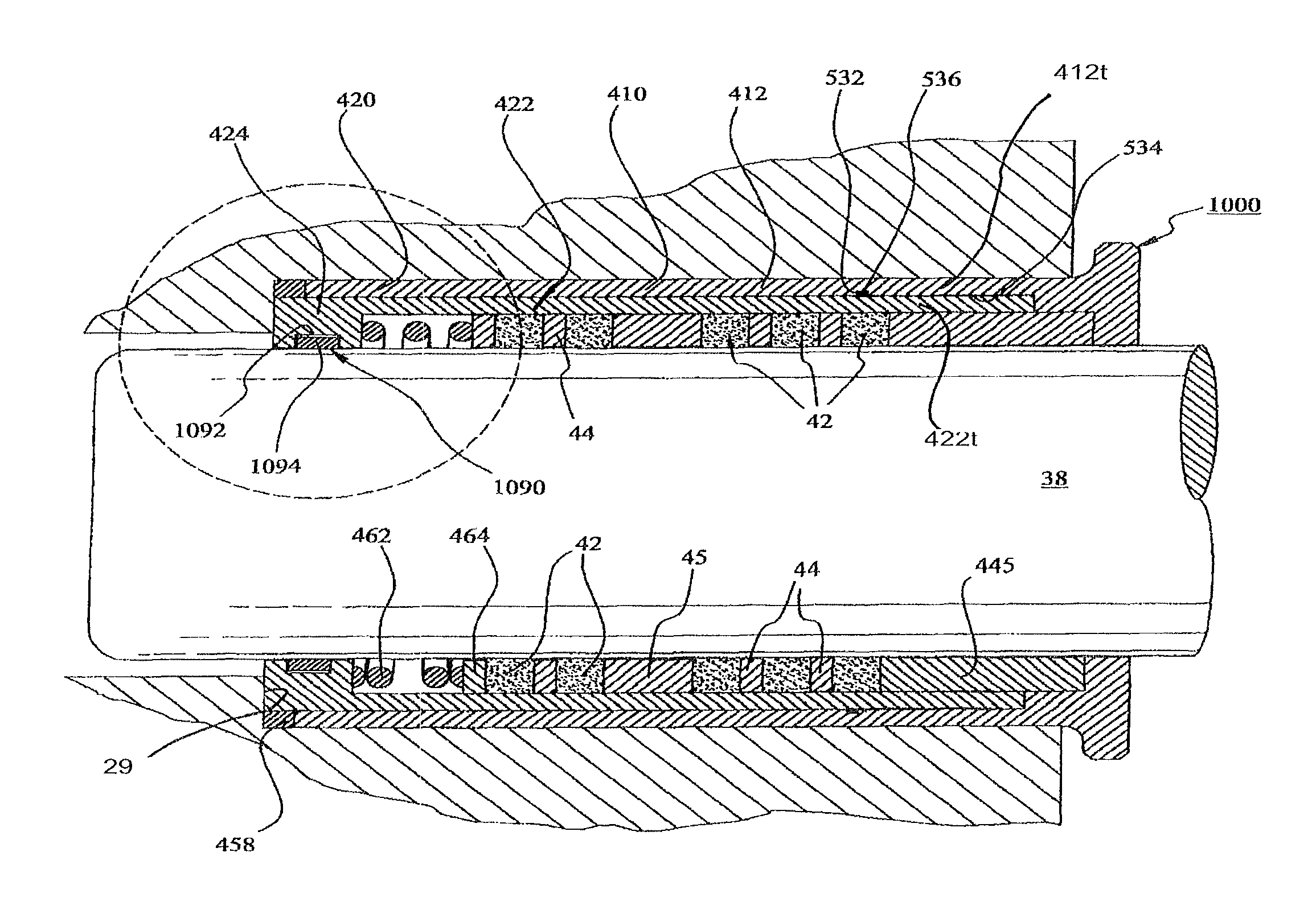
[0087]As defined herein, a “packing cartridge” is an apparatus that is adapted to be at least partially positioned in the packing bore of a plunger-type pump. As described below in more detail, the packing bore of the pump can be integrally formed in the fluid end or it can be provided by a stuffing box.

[0088]As used herein and in the appended claims, the words “comprise” and “include” and all grammatical variations thereof are each intended to have an open, non-limiting meaning that does not exclude additional elements or parts of an assembly, subassembly, or structural element.

[0089]As used herein, terms such as “first,”“second,”“third,” etc. are arbitrarily assigned and are merely intended to differentiate between two or more parts that are similar or corresponding in structure and / or function. It is to be understood that the words “first” and “second” serve no other purpose and are not part of the name or description of the following terms. Furthermore, it is to be understood th...


PUM


Abstract

A package cartridge is provided for use in the maintenance of a packing bore for a plunger-type pump. According to one aspect, a packing cartridge includes: a generally-cylindrical sleeve adapted to be at least partially positioned in the packing bore, a first abutment ring positioned in the sleeve, and a second abutment ring positioned in the sleeve and co-axially spaced apart from the first abutment ring. Telescoping structures are operatively positioned between the first abutment ring and the second abutment ring. According to another aspect, a structure forming a circumferential pressure-ring groove is provided. A pressure ring is positioned in the pressure-ring groove, the pressure ring having at least one smaller external dimension than an internal dimension of the pressure-ring groove, whereby at least one clearance is provided between the pressure-ring groove and the pressure ring. These aspects can be advantageously practiced together.

Description

CROSS-REFERENCE TO RELATED APPLICATIONS[0001]Not applicableSTATEMENT REGARDING FEDERALLY SPONSORED RESEARCH OR DEVELOPMENT[0002]Not applicableREFERENCE TO MICROFICHE APPENDIX[0003]Not applicableTECHNICAL FIELD[0004]The present invention generally related to positive-displacement pumps, and, more particularly, to plunger-type pumps. More particularly still, the invention related to the packing seals and assemblies for reciprocating plungers in such pumps. The invention also related to the maintenance and use of such fluid pumps.BACKGROUND[0005]A positive-displacement pump, sometimes referred to as a reciprocating fluid pump or as a reciprocating power pump, is a type of fluid pump driven by power from an outside source applied to the pump.[0006]There are several types of reciprocating power pumps. Typically, the pumps are classified as being plunger pumps or piston pumps. A plunger pump is differentiated from a piston pump in that a plunger moves past stationary packing, whereas a pi...

Claims


Application Information

Patent Timeline
Patent Type & Authority Patents(United States)
IPC IPC(8): F16J15/34F16J15/38
CPCF16J15/183
Inventor STANTON, EDDIE N.STRICKLAND, MICHAEL L.
Owner CL PACKING SOLUTIONS
Why Eureka
Try Eureka