Check patentability & draft patents in minutes with Patsnap Eureka AI!

RJ-45 connector

Inactive Publication Date: 2012-01-24
GOLD CHARM LTD
View PDF4 Cites 3 Cited by
  • Summary
  • Abstract
  • Description
  • Claims
  • Application Information

AI Technical Summary

Benefits of technology

"The present patent is about a new type of RJ-45 connector that solves the problem of inconvenient placement of light emitting diodes on the rear end of a computer or server chassis. The new connector has two light guide posts that are positioned on the top surface of the main body of the connector, making it easy to see the light generated by the diodes. The connector can be easily inserted into a motherboard connector and provides a secure connection. The technical effect of this new connector is improved visibility and convenience in network communication."

Problems solved by technology

However, in most cases, the interface is defined in a rear end of the chassis, thus light generated by the light emitting diodes is only seen from the back of the chassis, which is inconvenient.

Method used


Image

  • RJ-45 connector
  • RJ-45 connector
  • RJ-45 connector

Examples


Embodiment Construction

[0010]The disclosure, including the accompanying drawings in which like references indicate similar elements, is illustrated by way of examples and not by way of limitation. It should be noted that references to “an” or “one” embodiment in this disclosure are not necessarily to the same embodiment, and such references mean at least one.

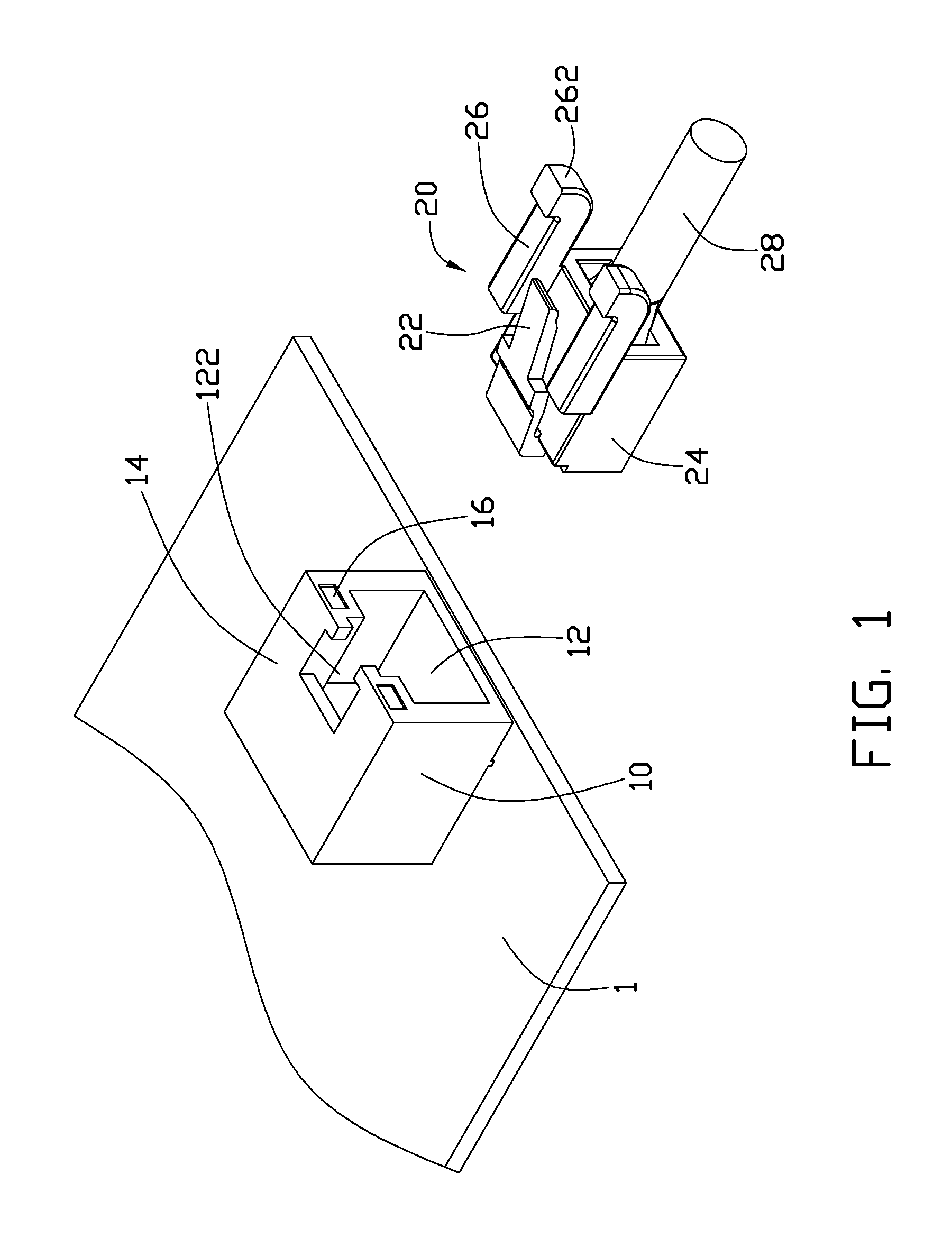
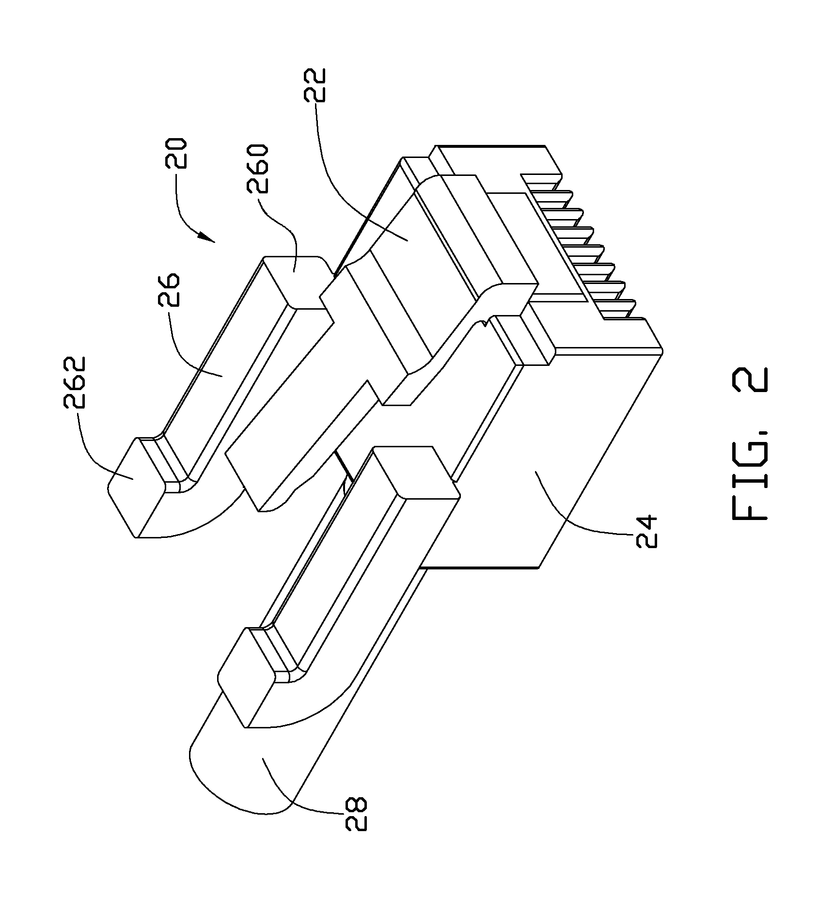
[0011]Referring to FIGS. 1, and 2, one embodiment of a Registered Jack-45 (RJ-45) connector 20 includes a main body 24, and a cable 28 extending from a first end of the main body 24.

[0012]An elastic latch 22 is formed on a second end of the main body 24 opposite to the first end and extends slantingly above a top surface of the main body 24. Two light guide posts 26 are formed on the top surface of the main body 24. The two light guide posts 26 are substantially parallel to and spaced apart from each other. The elastic latch 22 is positioned between the two light guide posts 26. Each light guide post 26 includes a first end 260 and a second end opposi...


PUM


Abstract

A Registered Jack-45 (RJ-45) connector matching a connector with two light emitting diodes includes a main body forming two light guide posts. Each light guide post includes a first end facing a corresponding light emitting diode, and a second end opposite to the first end. The light guide posts transmit light emitted by the light emitting diodes from the first ends to the second ends of the light guide posts.

Description

[0001]This relevant subject matter is disclosed in a co-pending U.S. patent application entitled “RJ-45 connector”, filed on Jun. 29, 2010, with application Ser. No. 12 / 825,339, which is assigned to the same assignee as this patent application.BACKGROUND[0002]1. Technical Field[0003]The present disclosure relates to a Registered Jack-45 (RJ-45) connector.[0004]2. Description of Related Art[0005]RJ-45 connectors are widely used in network communication. In use, an RJ-45 connector is engaged in an interface of a chassis of a computer or a server. The interface includes two light emitting diodes, used to indicate whether the network connection is working properly. However, in most cases, the interface is defined in a rear end of the chassis, thus light generated by the light emitting diodes is only seen from the back of the chassis, which is inconvenient.BRIEF DESCRIPTION OF THE DRAWINGS[0006]Many aspects of the present embodiments can be better understood with reference to the followi...

Claims


Application Information

Patent Timeline
Patent Type & Authority Patents(United States)
IPC IPC(8): H01R3/00
CPCH01R13/7175H01R24/64
Inventor SUN, ZHENG-HENG
Owner GOLD CHARM LTD
Features
  • R&D
  • Intellectual Property
  • Life Sciences
  • Materials
  • Tech Scout
  • Unparalleled Data Quality
  • Higher Quality Content
  • 60% Fewer Hallucinations
Learn More