Shooting mode switch control mechanism for nail gun

a control mechanism and shooting mode technology, applied in the field of nail guns, can solve the problems of large size and complicated structure of regular shooting mode control switch mechanisms, and achieve the effect of compact structur

Inactive Publication Date: 2012-02-07
CENT FASTENER
View PDF20 Cites 7 Cited by
  • Summary
  • Abstract
  • Description
  • Claims
  • Application Information

AI Technical Summary

Benefits of technology

[0007]The present invention has been accomplished under the circumstances in view. It is the main object of the present invention to provide a shooting mode switch control mechanism for use in a nail gun, which has the characteristic of compact structure.

Problems solved by technology

In consequence, regular shooting mode control switch mechanisms commonly have the drawbacks of large size and complicated structure.

Method used


Image

  • Shooting mode switch control mechanism for nail gun
  • Shooting mode switch control mechanism for nail gun
  • Shooting mode switch control mechanism for nail gun

Examples


Embodiment Construction

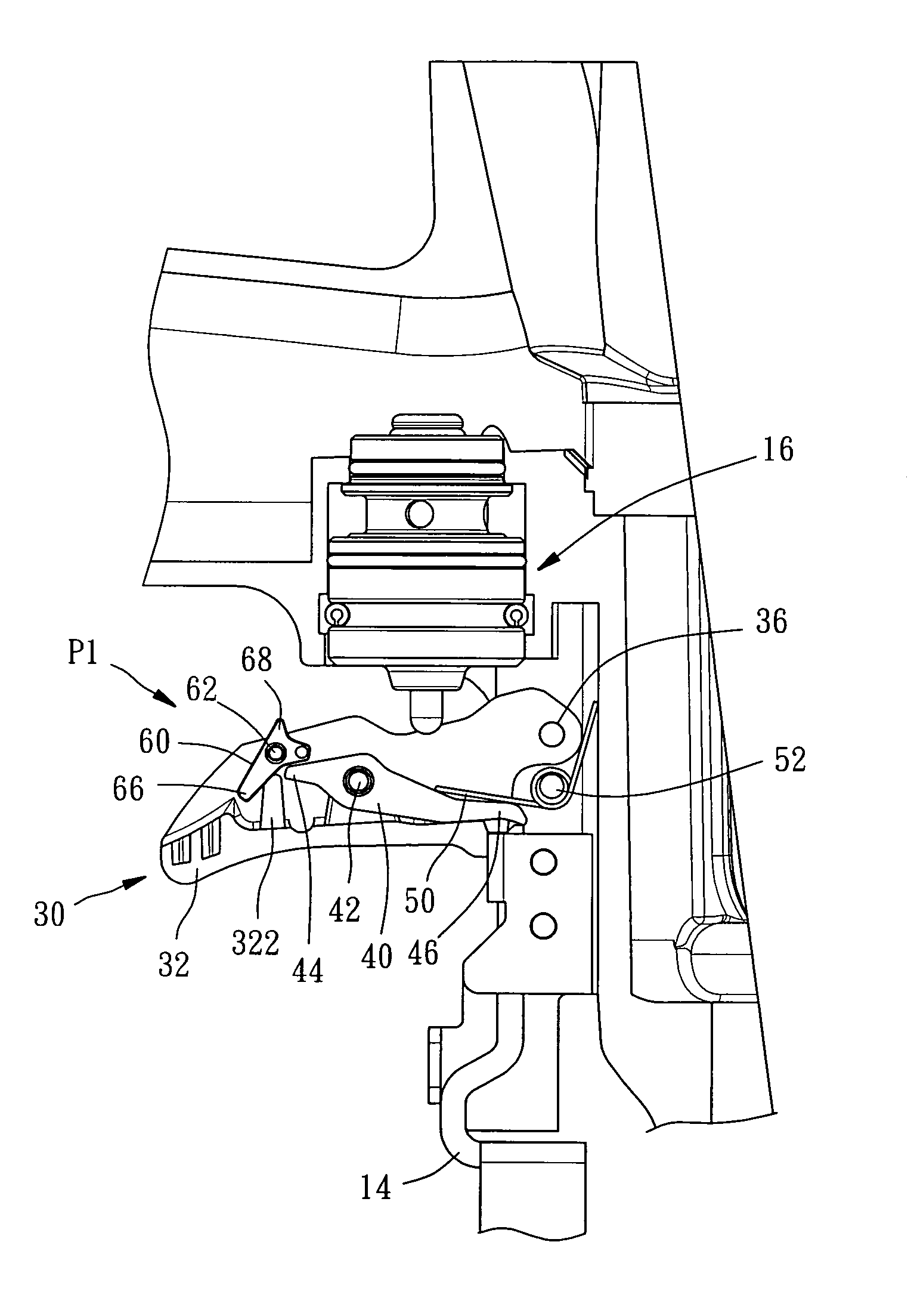
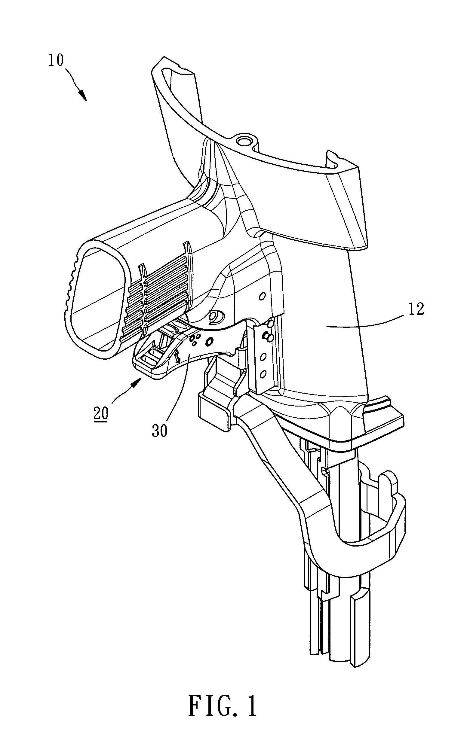
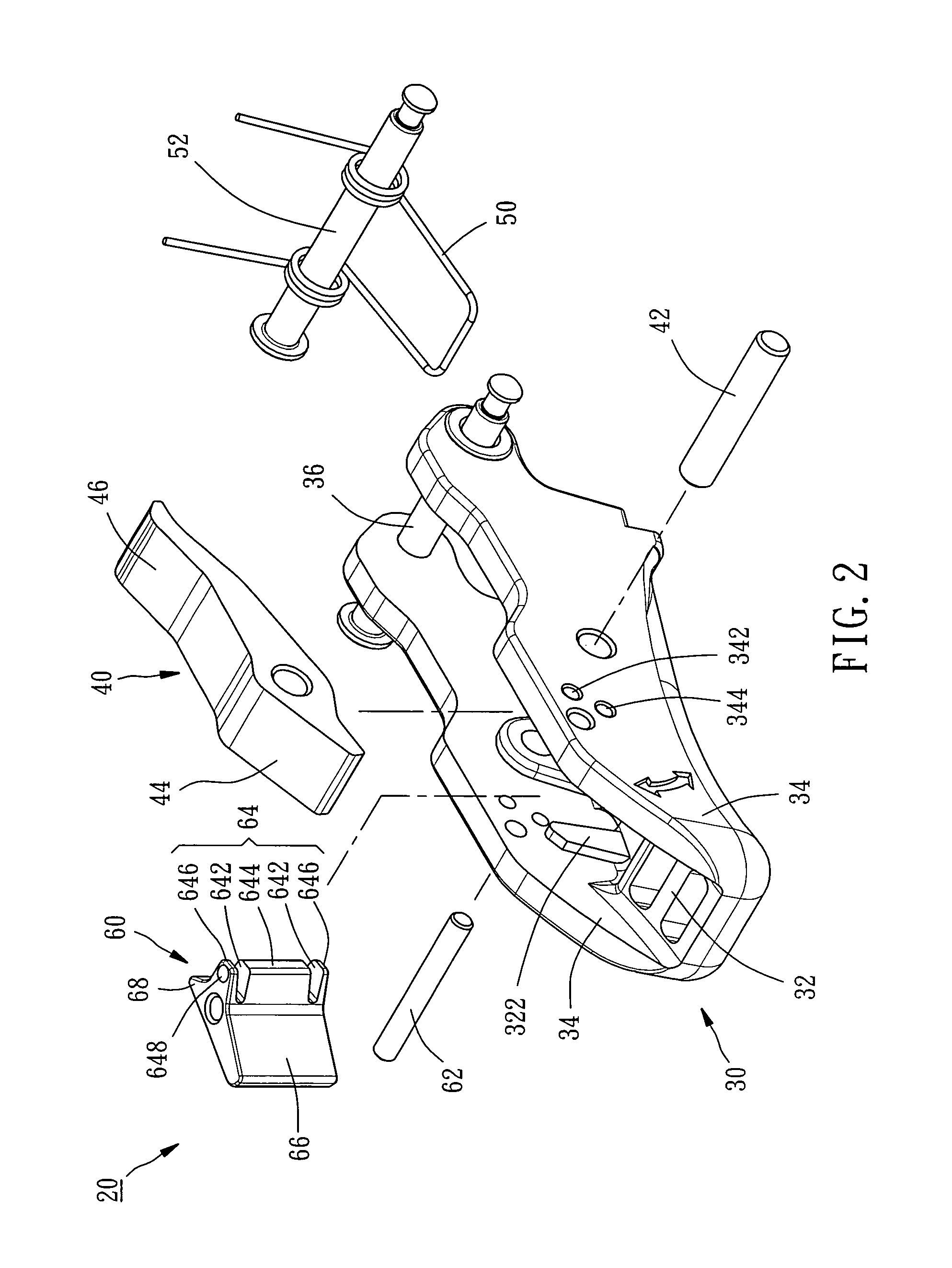
[0018]Referring to FIGS. 1˜3, a shooting mode switch control mechanism 20 used in a nail gun 10 in accordance with the present invention is shown comprising a trigger 30, a stop member 40, a spring member 50 and a switch 60.

[0019]The trigger 30 has a bottom wall 32, two opposing sidewalls 34, and two stop flanges 322 respectively protruded from the sidewalls 34. A pivot pin 36 is inserted through the two sidewalls 34 to pivotally connect the trigger 30 to the gun body 12 of the nail gun 10. Further, each sidewall 34 has a first hole 342 and a second hole 344.

[0020]The stop member 40 is pivotally connected between the two sidewalls 34 of the trigger 30 by a pivot pin 42, i.e., the stop member 40 has a first end portion 44 disposed at the left side relative to the pivot pin 42 and a second end portion 46 disposed at the right side relative to the pivot pin 42.

[0021]The spring member 50 is a torsional spring wound round an axle 52 in the gun body 12 and secured thereto. The spring memb...


PUM

PropertyMeasurementUnit
areaaaaaaaaaaa
forceaaaaaaaaaa
timeaaaaaaaaaa

Abstract

A shooting mode switch control mechanism used in a nail gun is disclosed to include a trigger, a lever function stop member pivotally mounted in the trigger, a spring member stopped against the stop member and a switch pivotally mounted in the trigger. The spring member and the switch are arranged at two sides relative to the pivoted area of the stop member so that when the switch is in the single-shooting position and the trigger is released, the second end portion of the stop member is forced by the spring member into the moving path of the safety bar and pushable by the safety bar for enabling the stop member to activate the air-valve switch once each time the trigger is pressed. When the switch is in the continuous-shooting position, the first end portion of the stop member is stopped against the switch for enabling the second end portion of the stop member to be continuously pushed by the safety bar to activate the air-valve switch continuously. By using the stop member to match with the left-sided switch and the right-sided spring member for controlling the biasing angle of the stop member, one single spring member can provide the necessary power for returning the stop member and the trigger, and therefore the invention has a compact structure characteristic.

Description

BACKGROUND OF THE INVENTION[0001]1. Field of the Invention[0002]The present invention relates to nail guns and more particularly, to a shooting mode switch control mechanism for use in a nail gun.[0003]2. Description of the Related Art[0004]To fit different working requirements, a nail gun is generally equipped with a shooting mode switch control mechanism for allowing switching between a single-shooting mode and a continuous-shooting mode.[0005]When the shooting mode control switch mechanism is switched to the single-shooting mode, the operator must stop the safety bar of the nail gun against the workpiece and then press the trigger to activate an air-valve switch for firing a nail. For firing a next nail, the operator must release the trigger and then press the trigger again. When the shooting mode control switch mechanism is switched to the continuous-shooting mode, the operator must keep the trigger in the pressed position and then continuously strike the safety bar against the ...

Claims


Application Information

Patent Timeline
Patent Type & Authority Patents(United States)
IPC IPC(8): B25C1/04
CPCB25C1/008B25F5/00
Inventor LIU, HSIEN-NUNGHO, YU-CHUAN
Owner CENT FASTENER
Why Eureka
Try Eureka