
Sprinkler mounting device

a technology of mounting device and sprinkler, which is applied in the direction of machine support, filing appliance, other domestic objects, etc., to achieve the effect of convenient mounting

Inactive Publication Date: 2012-02-07
KOFULSO
View PDF25 Cites 48 Cited by
  • Summary
  • Abstract
  • Description
  • Claims
  • Application Information

AI Technical Summary

Benefits of technology

"The present invention provides a sprinkler mounting device that can provide a strong and firm joining structure even when using a rectangular-shaped pipe as a support bar. The device includes T-shaped frames, support units, fastening screws, and a mounting bracket, among others. The mounting bracket is easy to install and includes a rotating member and tightening screws for securely mounting a reducer. The device allows for easy mounting work of the reducer and provides a strong and firm joining structure."

Problems solved by technology

Furthermore, as shown in FIG. 2, the separate type mounting device that the support bar 3 and the support units 2 are manufactured in a separate form has several problems in that it is structurally weak since the support bar 3 and the T-shaped frames 1 are assembled to the support units 2 in a forcedly-fitting manner, and in that a user has to hold the mounting bracket 4 with one hand standing on a foothold since there is no a means for supporting the mounting bracket 4 during mounting work of the reducer 5 in case that the open type mounting bracket 4 to be fit to the support bar 3 is used.

Method used


Image

  • Sprinkler mounting device
  • Sprinkler mounting device
  • Sprinkler mounting device

Examples


Embodiment Construction

[0020]Reference will be now made in detail to the preferred embodiment of the present invention with reference to the attached drawings.

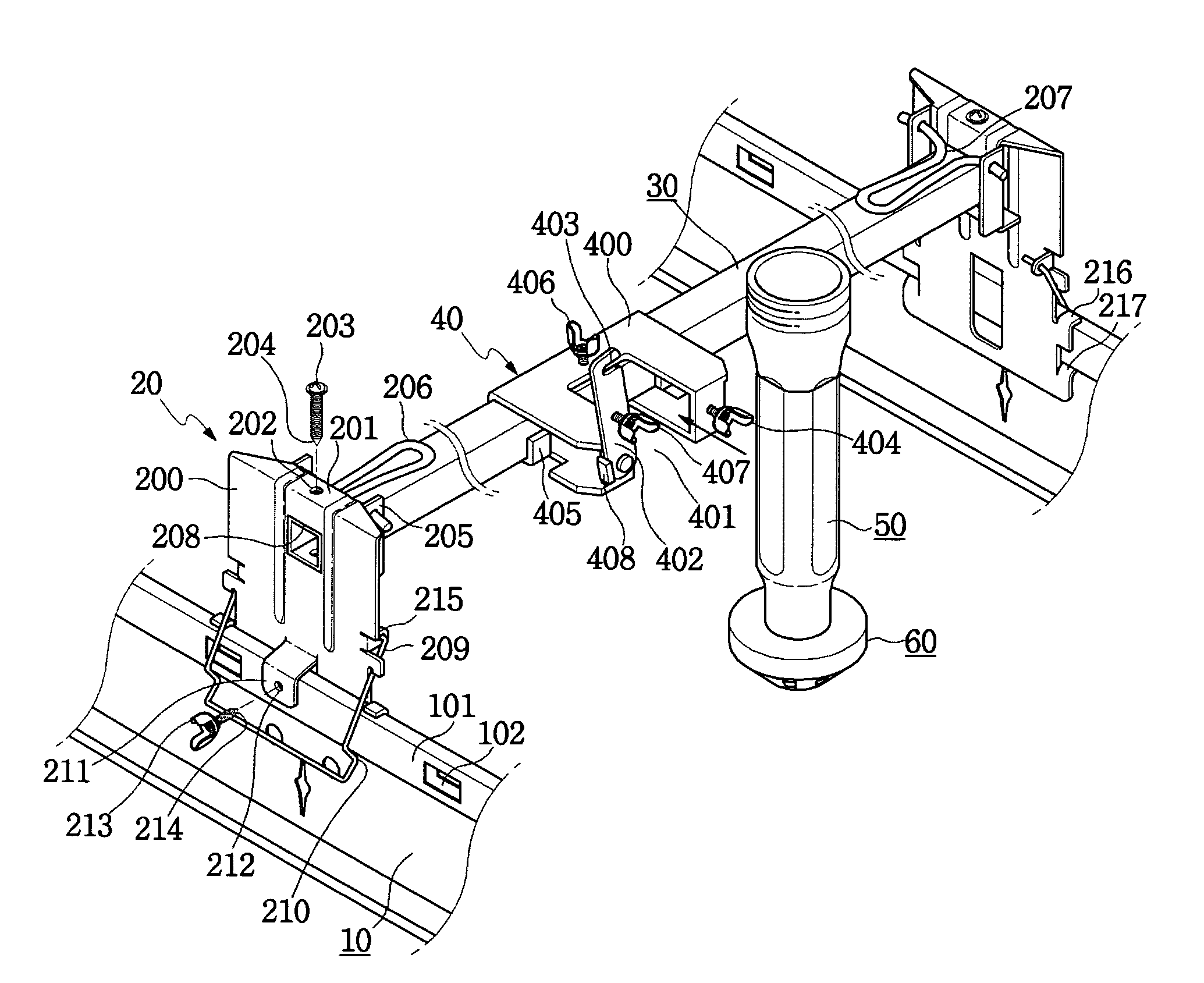
[0021]As shown in FIG. 3, a sprinkler mounting device includes: a pair of T-shaped frames 10 mounted on a ceiling parallel with each other at a predetermined interval; a pair of support units 20 perpendicularly standing and joined to the T-shaped frames 10; a support bar 30 disposed on upper portions of the support units 20 in such a way as to cross the T-shaped frames 10; and a mounting bracket 40 mounted on the support bar 30 in a laterally movable manner, so that a reducer 50 is joined thereto.

[0022]Each of the T-shaped frames 10 includes a projecting jaw portion 101 formed on an upper portion thereof and formed by an one-ply sidewall having a slot 102, and is unfit for joining the support unit 20 thereto using a fastening screw 213 having a sharp tip portion 214 since a lower portion of the projecting jaw portion 101 is relatively weak. For this...


PUM


Abstract

A sprinkler mounting device that support units are joined to T-shaped frames and a support bar through screws, thereby providing a strong and firm mounted state and preventing a separation of the support units from the support bar during work.

Description

BACKGROUND OF THE INVENTION[0001]1. Field of the Invention[0002]The present invention relates to a sprinkler mounting device that support units are joined to T-shaped frames and a support bar through screws, thereby providing a strong and firm mounted state and preventing a separation of the support units from the support bar during work even though the mounting device is in an open type that a reducer is fit into a mounting bracket from the front.[0003]2. Background Art[0004]In general, as shown in FIG. 1, a sprinkler mounting device includes: a pair of T-shaped frames 1 mounted on a ceiling parallel with each other at a predetermined interval; a pair of support units 2 perpendicularly standing and joined to the T-shaped frames 1; a support bar 3 disposed on upper portions of the support units 2 in such a way as to cross the T-shaped frames 1; and a mounting bracket 4 mounted on the support bar 3 in a laterally movable manner, so that a reducer 5 is joined thereto.[0005]Conventiona...

Claims


Application Information

Patent Timeline
Patent Type & Authority Patents(United States)
IPC IPC(8): B42F13/00
CPCA62C35/68B05B15/061B05B15/62
Inventor OH, SEUNG-IL
Owner KOFULSO
Features
  • Generate Ideas
  • Intellectual Property
  • Life Sciences
  • Materials
  • Tech Scout
  • Unparalleled Data Quality
  • Higher Quality Content
  • 60% Fewer Hallucinations
Learn More