
Electrocoagulation chamber and method

a technology of electrocoagulation chamber and electrocoagulation chamber, which is applied in the direction of fluid pressure measurement, liquid/fluent solid measurement, peptide measurement, etc., can solve the problems of increasing the complexity of the necessary equipment, increasing the cost of treatment, impurities and undesirable components, etc., and achieves the reduction of cost and complexity, improved efficiency, and low cost

Inactive Publication Date: 2003-09-02
GILMORE F WILLIAM
View PDF6 Cites 68 Cited by
  • Summary
  • Abstract
  • Description
  • Claims
  • Application Information

AI Technical Summary

Benefits of technology

The method includes controlling the flow of process liquid through the chamber by interposing a baffle between the electrode blades and second end of the chamber. The baffle closes the second end of the channel to at least the predetermined height of the electrode blades within the chamber, thereby ensuring that process liquid covers the blades.
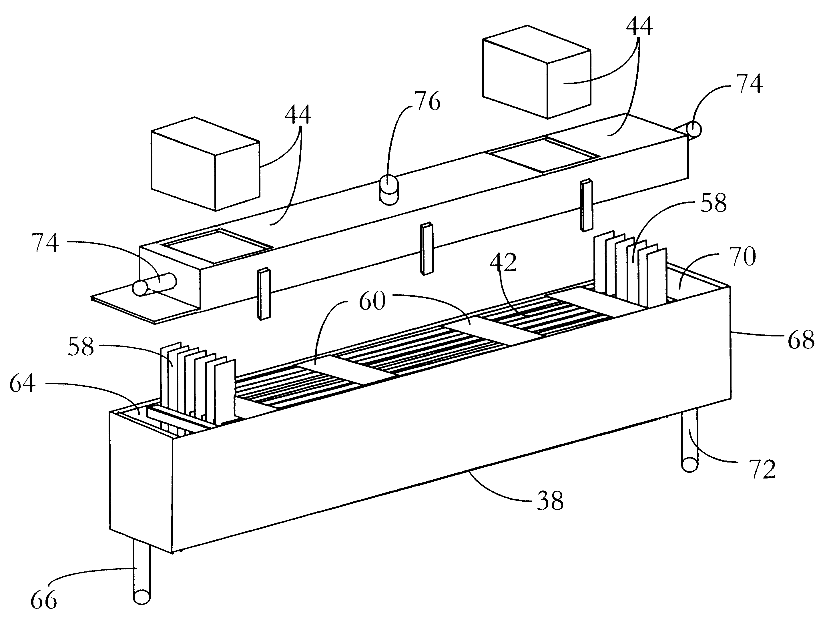
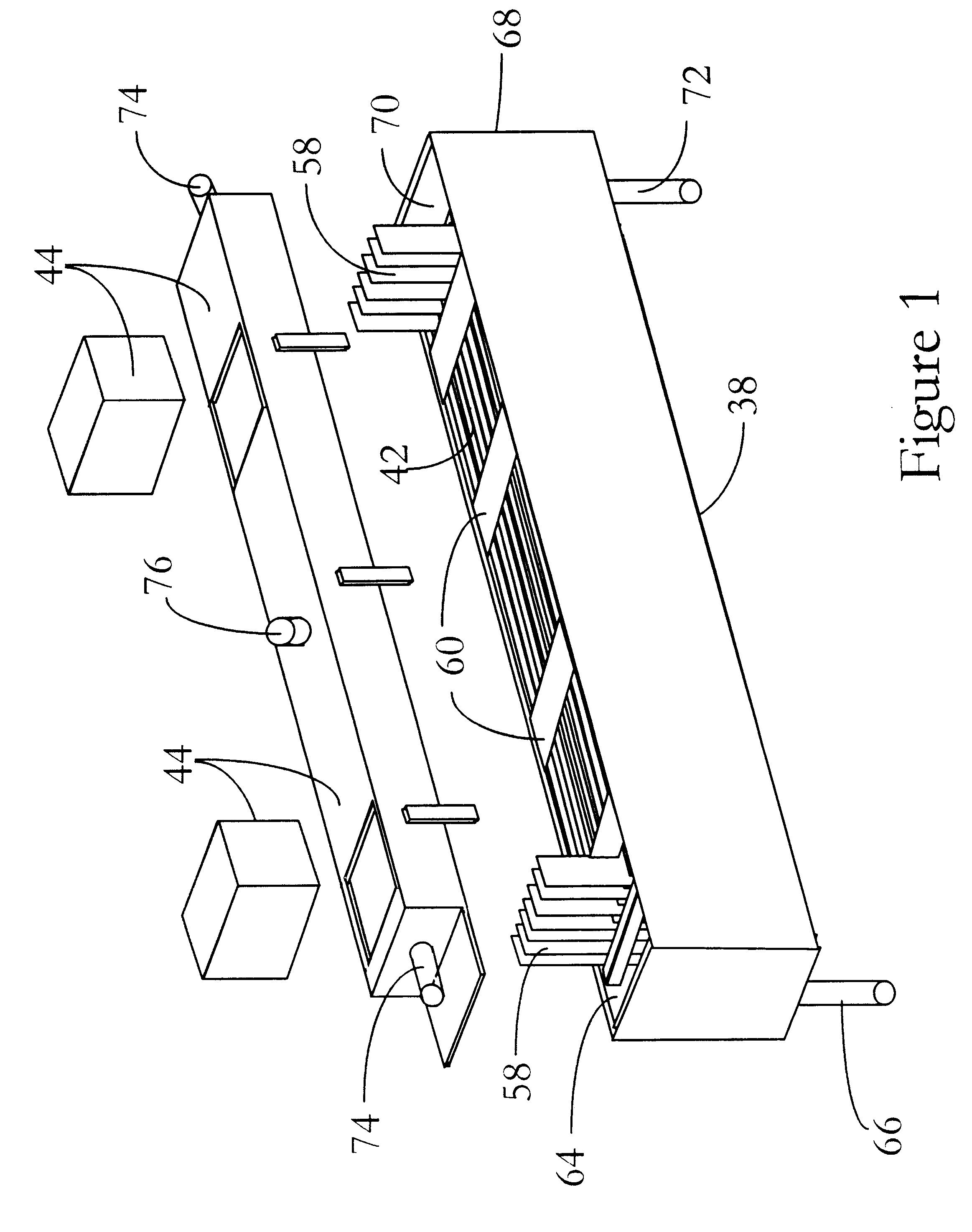
The invention provides a unique horizontal flow reaction chamber with reaction blades having their major dimension horizontally oriented for treating water by electrocoagulation. This orientation of the reaction blades solves a number of a significant problems in the art. Among these, the configuration provides a substantially larger surface area on top of the liquid in the reaction chamber for enabling foam and gases to escape from the treated water and be removed from the processing system. A horizontal blade disposition also greatly simplifies maintenance because the reaction blades can be serviced by lifting a blade a minor distance such as 30.5 cm (1 ft.), in contrast to lifting a blade a major distance as 122 cm (4 ft.) as required in an equivalent vertical flow system. By disposing the blades with their major dimension in a horizontal direction, it becomes possible as well as practical to treat waste streams having a requirement for a significantly greater degree of treatment. For example, unusually long blade lengths, such as 1.83 m, 2.44 m, and 3.05 m long (6, 8, or 10 feet long) now can be utilized in a facility having little or no special structural adaptation to receive the chamber and provide adequate overhead room for servicing the blades.
A horizontal system can utilize improved blade guides formed as discrete portable units that are removable from the reaction chamber independently of the reaction blades. Because the chamber is horizontal, it has a large amount of top access as compared to its depth. Thus, it is easy to work with discrete portable blade guides that are positioned on the bottom of the chamber and receive the lower edges of the blades. Similar discrete portable blade guides are placed over the top of the blades. The guides are desired to be small, both because they will be easy to handle and because it is desirable to leave open space on top of the blades for venting hydrogen and other gases or foam. It is preferred that the top blade guides cover no more than twenty-five percent of the top edges of the blades, so that a substantial portion of the reaction chamber is in open communication with the disbursement chamber.
Unitary blade guides employ one or more independent top blade guides and bottom blade guides. These independent guides enable improved simplicity in removing blades for cleaning or replacement. The top blade guides can be removed independently of the bottom guides, allowing the array of reaction chamber blades to collapse laterally. This collapse provides improved access to the blades and allows each one to be gripped for removal. In contrast, a fixed groove system provides a narrow access, such as only 0.32 cm (1 / 8 in.) between blades.
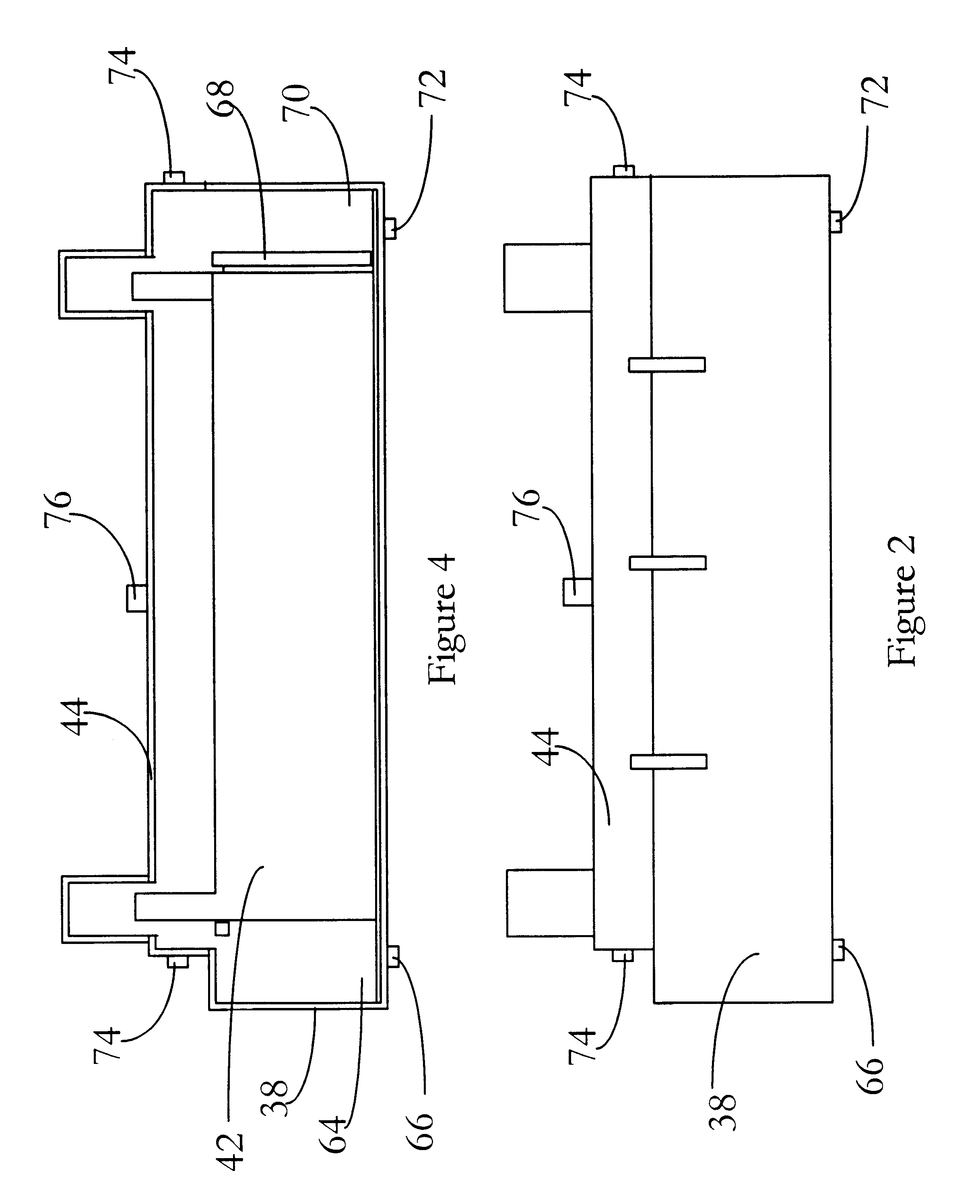
Foam and gas removal in a horizontal system is conducted with improved efficiency. The processing system is conducted at ambient pressure and is not required to be sealed from the atmosphere, although the foam and gas removal system employs a hood or lid that defines a disbursement chamber over the reaction chamber. At ambient pressure, foam and gas are removed by a two-sided gas sweeping system. Air is supplied under pressure into the disbursement chamber from entry ports at one or both ends of the chamber. A low vacuum, which can be supplied at low cost, is applied at a vacuum exit port that is spaced from the entry port, establishing a gas sweeping pattern between the entry and exit ports in the disbursement chamber.
Both foam and gas are picked-up in the air flow and removed through the vacuum exit port. The removal of foam and gas through a different exit than the processed liquid provides a significant reduction in the cost and complexity of any downstream secondary separation system. This early separation and removal of foam and gas largely is enabled by the horizontal character of the processing system, which supplies a large surface area on top of the reaction chamber, as compared to the volume of the chamber. A related advantage of the large surface area is that hydrogen build-up on the reaction blades is reduced, further lower operational cost.

Problems solved by technology

While this process is effective, it involves a series of problems that increase the complexity of the necessary equipment and increase the cost of treatment.
An initial problem is that in addition to the basic separation into water and agglomerate, it is common for an electrolytic treatment involving water to produce electrolysis of the water into hydrogen and oxygen, which must be removed for safety reasons.
This foam contains impurities and undesirable components that must be removed from the treated water.
Processing foam in such a downstream treatment apparatus can add substantially to the cost of treatment.
Such a vacuum source supplies high vacuum and is quite expensive in its power consumption.
A substantial cost of treatment is the high vacuum system, which often uses more power than the reaction chamber itself and all of the pumps used in a typical system.
In most applications, electrolytic treatment is considered costly both in consumption of electricity and in consumption of electrodes.
A problem that substantially increases cost is hydrogen deposition on the electrodes.
Hydrogen interferes with the efficient use of electricity and increases power requirements.
Several problems are inherent to vertical orientation.
Both create a problem in that they are costly and awkward.
However, the requirements of a vertical blade reaction system leave little choice.
While the grooved wall system is effective, it creates a problem in flexibility for different applications.
The reaction chamber is not well suited to use a different size or number of blades, and the gap between blades cannot readily be altered.
However, since a vertical reaction chamber tends to be quite deep and not very wide, it appears necessary to guide the blades with a structure that can be engaged at the top of the chamber.
The primary problem with a bundle is the bundle, itself.
It tends to be heavy and difficult to manipulate.

Method used


Image

  • Electrocoagulation chamber and method
  • Electrocoagulation chamber and method
  • Electrocoagulation chamber and method

Examples


Embodiment Construction

of the Primary Components:

A preferred surge tank 24 has sufficient capacity to hold a predetermined minimum reserve of liquid, such as 5 minutes of liquid 18, based upon the system flow rate. When chemical enhancement additives are used, a static mixer is provided in the tank to ensure the additives are thoroughly mixed in the liquid. When ozone is added, an ozone diffuser is located in the surge tank, and when oxygen added, a micro-bubbler is located in the bottom of the tank.

The chemical enhancement additives most commonly are acidic or caustic chemicals that alter the pH of the liquid. When a pH adjustment is needed, the acid or caustic is pumped into the surge tank by metering pump 30, which is controlled by a pH probe in the surge tank. Other chemicals can be added in a similar way, in some instances by a metering pump controlled by a timer in the PLC control system 56.

The ozone generator 36 is sized according to the flow rate of the liquid 18. This additive is used to treat co...


PUM

PropertyMeasurementUnit
distanceaaaaaaaaaa
distanceaaaaaaaaaa
distanceaaaaaaaaaa

Abstract

A stream of process liquid is treated while flowing through in a horizontally elongated chamber having an open top. Longitudinally elongated electrode blades are aligned with the longitudinal dimension of the chamber. An overhead disbursement chamber supplies a sweeping air stream over the open top of the chamber for removing foam and gas reaction by-products. The electrode blades are separated and held at a desired spacing by small portable guides located below and above the blades.

Description

The invention generally relates electrical chemistry and to processes and A compositions used for electrolysis. More specifically, the invention relates to electrolytic material treatment of water, sewage and other waste water. Another aspect of the invention relates to liquid purification and separation utilizing electrical or wave energy.The separation of an aqueous solution into water and an agglomerate can be accomplished by applying a voltage across the solution. While this process is effective, it involves a series of problems that increase the complexity of the necessary equipment and increase the cost of treatment. An initial problem is that in addition to the basic separation into water and agglomerate, it is common for an electrolytic treatment involving water to produce electrolysis of the water into hydrogen and oxygen, which must be removed for safety reasons. In addition, such treatment produces a foam on top of the liquid in the electrolytic treatment chamber. This fo...

Claims


Application Information

Patent Timeline
Patent Type & Authority Patents(United States)
IPC IPC(8): C02F1/463C02F9/00C02F1/461C02F1/00C02F1/78C02F1/66C02F1/465
CPCC02F1/463C02F1/465C02F1/66C02F1/78C02F9/00C02F2001/46152C02F2201/4611C02F2209/005C02F2301/063C02F2303/12
Inventor GILMORE, F. WILLIAM
Owner GILMORE F WILLIAM
Learn More