
Recording medium, recording apparatus, reproducing apparatus, and reproducing method

a recording medium and signal technology, applied in the direction of digital recording, maintaining head carrier alignment, instruments, etc., can solve the problems of adverse influence on subsequent data reproduction, difficult reproduction in the direction opposite to the recording direction, and inability to anticipate favorable reproduction of preamble and data signals, etc., to simplify the processing of the detecting section, and improve the accuracy of synchronization detection.

Inactive Publication Date: 2012-02-07
SONY CORP
View PDF16 Cites 7 Cited by
  • Summary
  • Abstract
  • Description
  • Claims
  • Application Information

AI Technical Summary

Benefits of technology

[0036]In view of the circumstances as described above, there is a need for a recording medium, a recording apparatus, and a reproducing apparatus that are capable of favorably carrying out data reproduction processing in both the forward direction and the backward direction.
[0053]As described above, according to the embodiments of the present invention, it is possible to correct the positional relationship between the unit and the reproducing head in the track width direction when forwarding the reproducing head in the track width direction for switching the unit to be reproduced, and thus favorably carry out data reproduction processing.

Problems solved by technology

Therefore, signals of the preamble and data cannot be expected to be favorably reproduced by the reproduction in the direction opposite to the recording direction.
Particularly when a track width is narrowed for increasing a recording density, it is expected that a degree of an influence of a positional deviation of the reproducing head from the track on the reproduction increases and the reproduction in the direction opposite to the recording direction thus becomes difficult.
Therefore, when a position of the reproducing head with respect to the track in the track width direction is deviated from its proper position at a point when the reproduction of the unit is finished to the end, a deviation amount thereof is carried over to a positional relationship between the next unit and the reproducing head, thus imparting an adverse influence on subsequent data reproductions.

Method used


Image

  • Recording medium, recording apparatus, reproducing apparatus, and reproducing method
  • Recording medium, recording apparatus, reproducing apparatus, and reproducing method
  • Recording medium, recording apparatus, reproducing apparatus, and reproducing method

Examples


first embodiment

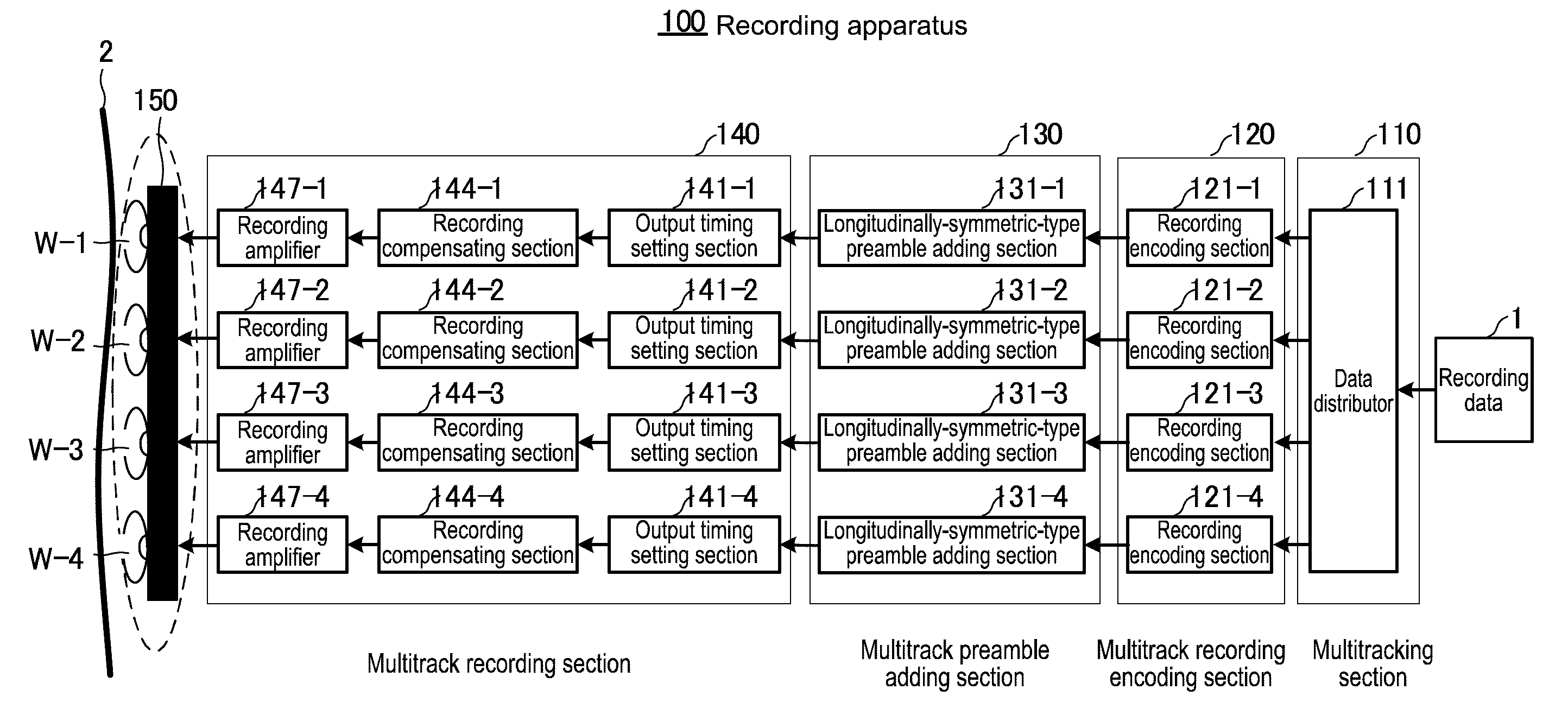
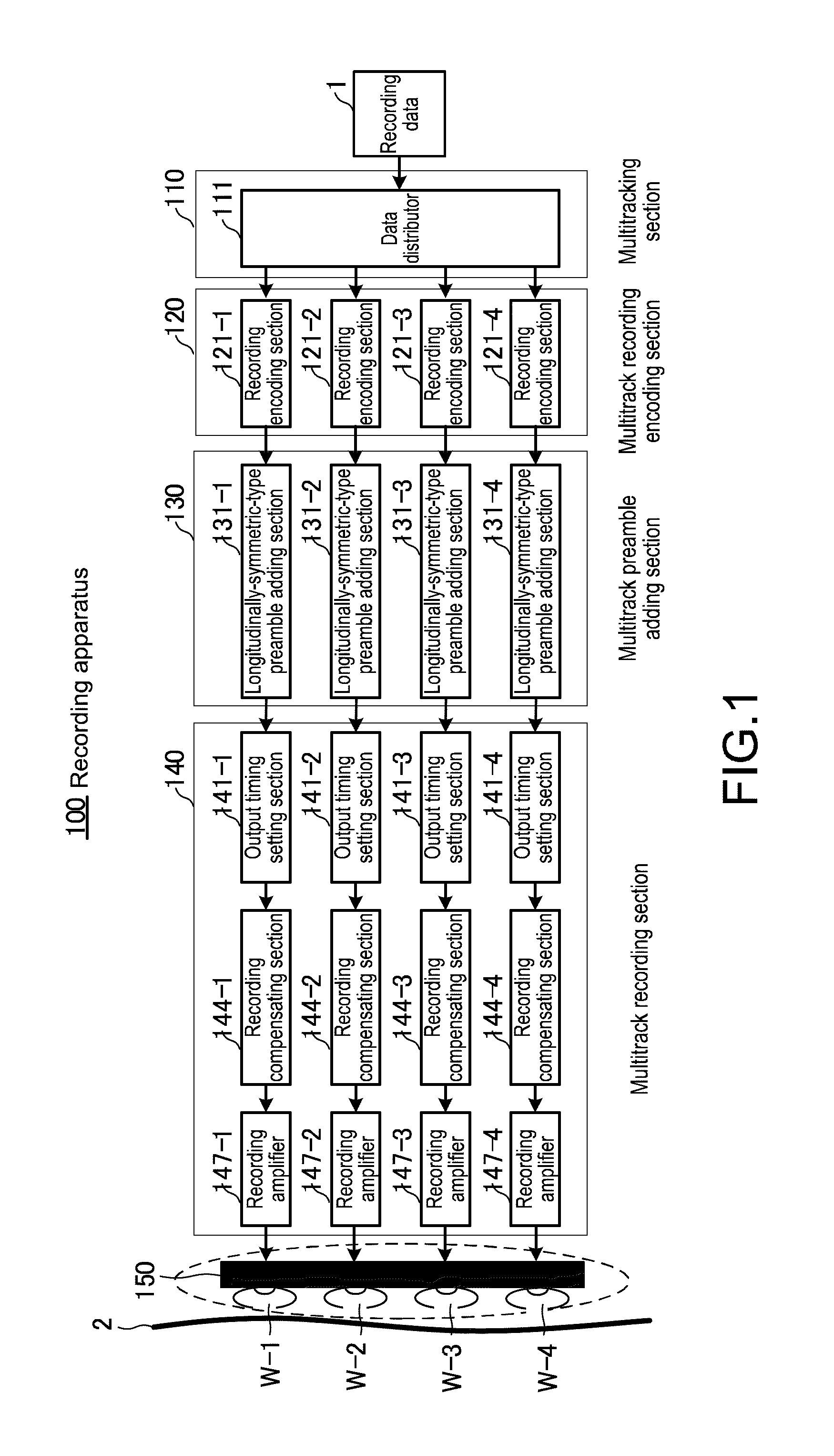
[0093]FIG. 1 is a diagram showing a structure of a recording apparatus in a magnetic recording / reproducing system that uses a multihead according to a first embodiment of the present invention. A recording apparatus in this magnetic recording / reproducing system is an apparatus that records a signal onto a tape-like magnetic recording medium without aligning a recording position for each track, and a reproducing apparatus of this magnetic recording / reproducing system is an apparatus that reproduces the signal from the magnetic recording medium without aligning a reproduction position for each track. Here, the number of recording heads is represented by M, and the number of reproducing heads is represented by N. In this embodiment, M and N are both set to 4.

[0094]As shown in the figure, a recording apparatus 100 is constituted of a multitracking section 110, a multitrack recording encoding section 120, a multitrack preamble adding section 130, a multitrack recording section 140, and a...

modified example 1 of first embodiment

[0214]Next, a modified example of the first embodiment will be described.

[0215]In the above embodiment, for example, at the time of the reproduction in the forward direction, the multiple-preamble processing controller 238 has detected the gain control patterns 41-5, 41-6, 41-7, and 41-8 in the third preamble 25, calculated the second gain with respect to the reproduction signals of the reproducing heads R-1, R-2, R-3, and R-4 based on the reproduction signals of the gain control patterns 41-5, 41-6, 41-7, and 41-8, and output the second gain to the reproduction signal gain control processor 233. On the contrary, in this modified example, at the time of the reproduction in the forward direction, it is also possible for the multiple-preamble processing controller 238 to receive an input of the first gain with respect to the reproduction signals of the reproducing heads R-1, R-2, R-3, and R-4 obtained based on the reproduction signals of the gain control patterns 41-1, 41-2, 41-3, and...

modified example 2 of first embodiment

[0216]A modified example of the multiple-preamble processing controller 238 will be described below as a modified example 2 of the first embodiment.

[0217]At the time of the reproduction in the forward direction, for example, the multiple-preamble processing controller 238 may estimate head positions of the synchronization patterns 42-5, 42-6, 42-7, and 42-8 in the third preamble 25 based on a result of the detection of the synchronization patterns 42-1, 42-2, 42-3, and 42-4 in the first preamble 23, and output information thereof to the synchronization signal detecting section 231. In this case, the synchronization signal detecting section 231 detects the synchronization patterns 42-5, 42-6, 42-7, and 42-8 in the third preamble 25 based on the information output from the multiple-preamble processing controller 238 and readjusts the captured synchronization based on the previously-detected synchronization patterns 42-1, 42-2, 42-3, and 42-4 in the first preamble 23.

[0218]It should be...


PUM

PropertyMeasurementUnit
widthaaaaaaaaaa
timeaaaaaaaaaa
recording densityaaaaaaaaaa

Abstract

Provided is a recording medium onto which a plurality of tracks that constitute a unit as one unit of signal processing for reproducing data are recorded, each of the plurality of tracks being recorded with at least data and, as a preamble necessary for controlling the reproduction of the data, a separation pattern necessary for detecting a positional relationship between a reproducing head and the plurality of tracks in a track width direction and synchronization patterns for synchronization processing, the synchronization patterns being recorded in front and rear of the separation pattern in a running direction of the plurality of tracks.

Description

BACKGROUND OF THE INVENTION[0001]1. Field of the Invention[0002]The present invention relates to a reproducing apparatus and method for reproducing signals from a recording medium onto which a plurality of tracks are recorded using one or a plurality of reproducing heads.[0003]2. Description of the Related Art[0004]In magnetic recordings and reproductions in recent years, an additional increase in a recording density is demanded along with an increase in a capacity of magnetic recording systems. However, if a track width is narrowed so as to obtain a high recording density, there is a problem that it becomes difficult to obtain sufficient tracking performance at a time of the reproduction. In this regard, a non-tracking system capable of reading a signal from a track even when a position of a reproducing head is somewhat deviated from the track is proposed. For appropriately obtaining a reproduction signal in the non-tracking system, however, a strict restriction is placed on a sett...

Claims


Application Information

Patent Timeline
Patent Type & Authority Patents(United States)
IPC IPC(8): G11B5/584
CPCG11B5/00839G11B5/535G11B5/09
Inventor NAKAGAWA, TOSHIYUKI
Owner SONY CORP
Learn More