Pre-assembled internal shear panel

a shear panel and pre-assembled technology, applied in the direction of building components, building types, constructions, etc., can solve the problems of affecting the strength of the wall, the upper section of the wall moving relatively, and the wall collapsing, so as to reduce the tendency of steel sheets to buckle, reduce the movement of the upper plate, and simplify the installation of the preferred embodiment of the shear panel

Inactive Publication Date: 2012-02-14
SIMPSON STRONG TIE
View PDF277 Cites 24 Cited by
  • Summary
  • Abstract
  • Description
  • Claims
  • Application Information

AI Technical Summary

Benefits of technology

[0013]The side, top and bottom members of the shear panel are all attached to form a preferably rectangular frame of which the upper member of the panel is connected to an upper plate of the wall. This results in a shear panel capable of opposing lateral forces in the plane of the wall so as to reduce movement of the upper plate of the wall with respect to the lower plate.
[0014]In one preferred embodiment, the posts are formed out of a plurality of light gauge steel members and there are two sheets of sheet steel forming a diaphragm that are attached to both of the posts substantially along the full length of the posts and to the top and bottom frame members, with one sheet on each side of the frame. Further, there is preferably at least one reinforcing member which interconnects the posts positioned between the upper and lower member and between the two sheets forming the diaphragm members. The reinforcing member stiffens the side members and reduces the tendency for the steel sheets to buckle when the shear panel is under load.
[0015]The shear panel of the preferred embodiment is attached at the bottom corners to holdown bolts which are anchored in the foundation of the building and the bottom member of the steel frame is fastened to the concrete foundation with a minimum of two anchor bolts or approved fasteners. The upper member of the shear panel of the preferred embodiment is connected to the upper plate of the frame of the wall so that lateral forces in the plane of the wall are transmitted to the shear panel. Because the lateral force is applied through the top plate there is an overturning effect on the panel that is resisted by the end posts, holdown assembly and anchor bolts. The horizontal shear force is resisted by the additional anchor bolts or fasteners in the bottom frame members. In one preferred embodiment, a gusset is used to attach the upper member of the shear panel to the upper plate of the frame of the wall. Further, in the preferred embodiment additional shear bolts are mounted through the lower member of the shear panel into the foundation of the building to reduce the likelihood that the shear panel will become dismounted at the bottom end from the foundation as a result of shear forces applied against the wall.
[0016]The shear panel of the preferred embodiment is preferably shipped to the job site substantially assembled. The installer simply has to attach the mounting brackets to the holdown bolts that are anchored in the foundation and then position the lower member of the shear panel in the brackets. Subsequently, the installer has to secure the lower member of the shear panel to the brackets, and, hence, to the concrete foundation with cast-in-place anchor bolts or other approved fasteners. Subsequently, the remainder of the shear panel can be attached to the lower member. Further, the upper member of the shear panel can then be attached to an upper portion, e.g., the upper plates, of the wall. Hence, installation of the shear panel of the preferred embodiment is simplified over constructing an appropriate shear panel in the field during the construction of the building.
[0017]In addition, the configuration and metal construction of the shear panel of the preferred embodiment results in a shear panel that is capable of withstanding greater amounts of shear forces than the shear panel structures of the prior art. This allows the shear panel of the preferred embodiment to be smaller in size, e.g., have a smaller width, which allows the shear panel to be installed along smaller wall sections without a decrease in the amount of protection against lateral forces. These and other objects and features of the present invention will become more fully apparent from the following description and appended claims taken in conjunction with the accompanying drawings.

Problems solved by technology

One problem that occurs in buildings is that lateral forces applied in a direction parallel to, and in the plane of, the wall can cause the upper section of the wall to move relative to the lower plate which is anchored to the foundation.
It will be evident that too much movement of the upper sections of the wall relative to the anchored lower plate can result in damage to the frame of the wall which can further result in the wall collapsing.
It will be appreciated that constructing these structures in the field can be time consuming and can also result in construction errors that will affect the strength of the wall.
Further, these types of shear panels and, in particular, the plywood shear panels used in wooden framed buildings, must be comparatively large to withstand the significant amount of lateral forces that are generated in large earthquakes.
While on long walls there may be the space available between openings to position a 4-foot long or greater shear panel, in smaller buildings with smaller lengths of walls, there is often no room to construct a shear panel of this size.
This exacerbates the problem of a limited amount of space in walls of smaller lengths.

Method used


Image

  • Pre-assembled internal shear panel
  • Pre-assembled internal shear panel
  • Pre-assembled internal shear panel

Examples


Embodiment Construction

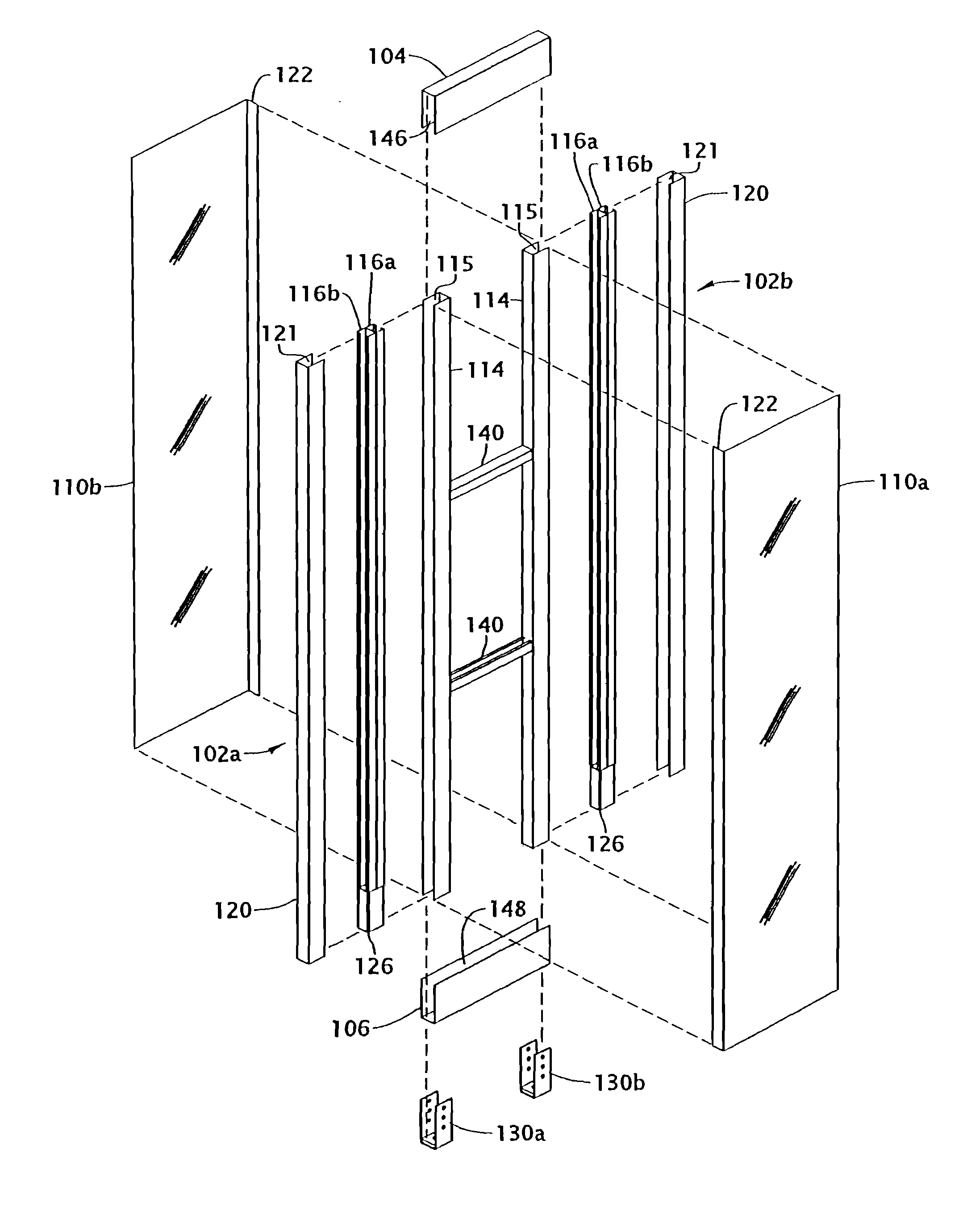
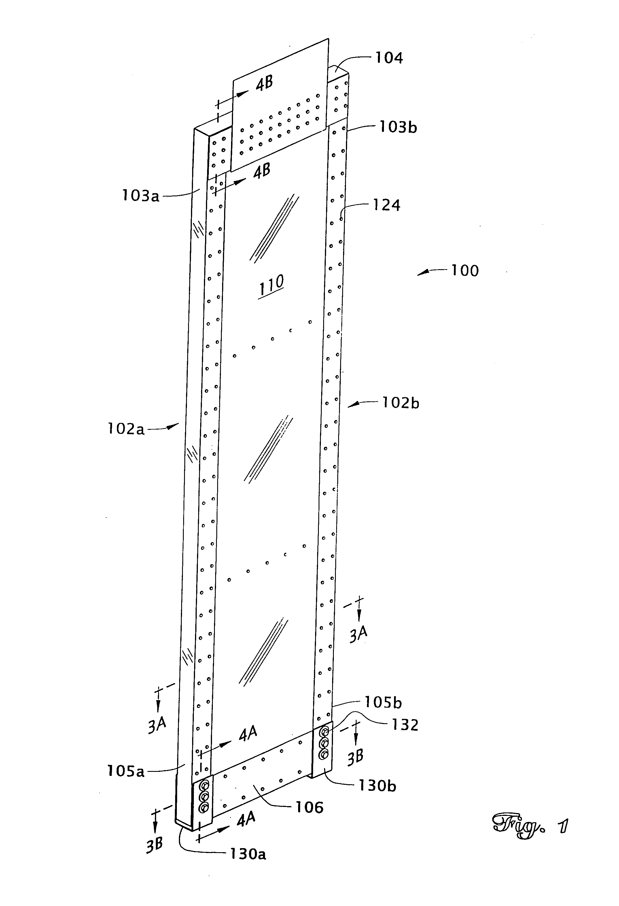
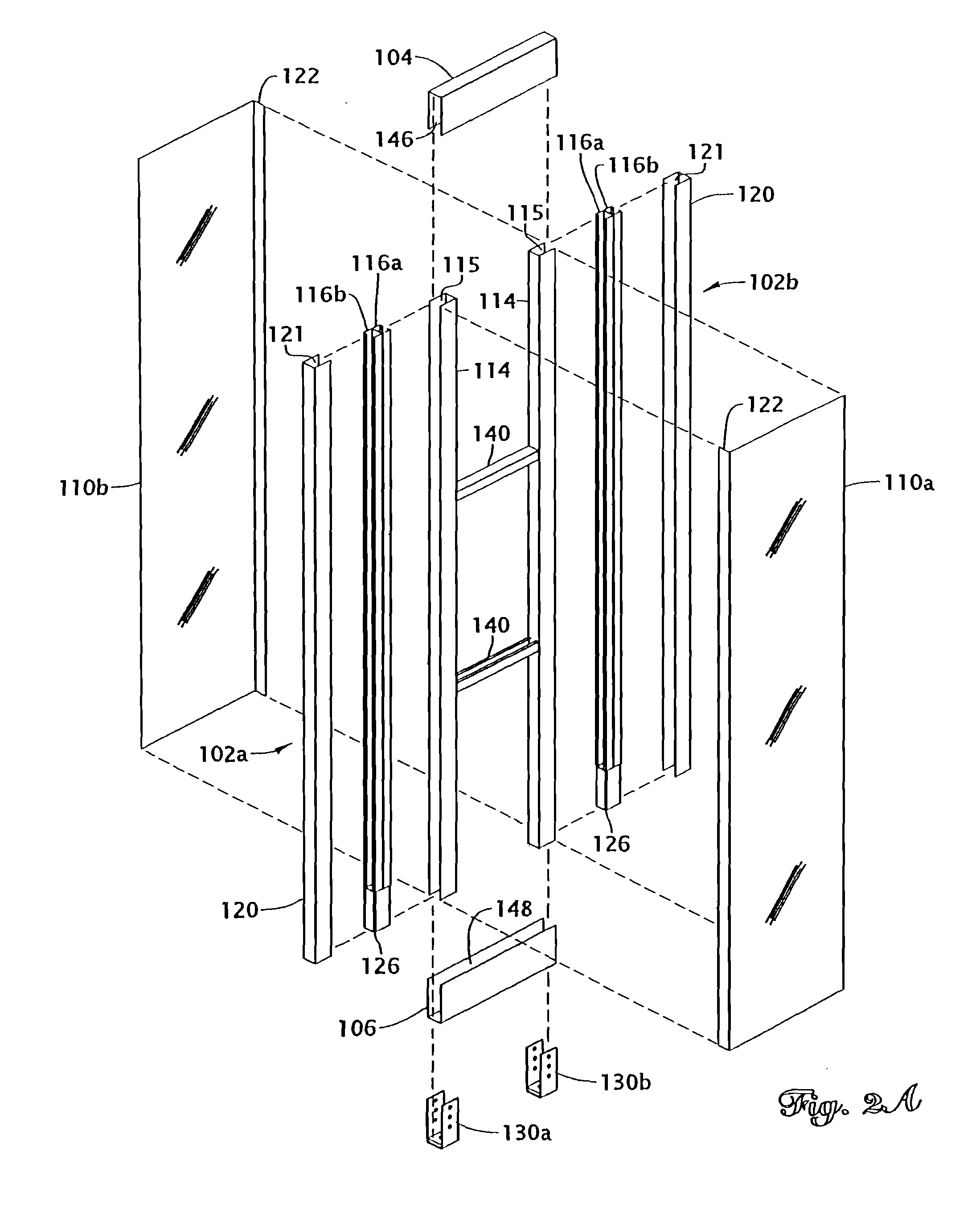
[0029]Reference will now be made to the drawings wherein like numerals refer to like parts throughout. FIG. 1 is a perspective view of a shear panel 100 of the preferred embodiment that is used to reduce the relative motion of an upper section of a wall relative to a bottom section of a wall in response to lateral forces that project in a direction along the length of the wall. The construction of the preferred embodiments of the shear panel 100 will initially be described in reference to FIGS. 1-4 and the installation and operation of the shear panel 100 of the preferred embodiments will be described in reference to FIGS. 5-7.

[0030]Referring initially to FIG. 1, a shear panel 100 of the preferred embodiment is shown. FIG. 1 illustrates the preferred configuration of the shear panel 100 in an assembled form as it is shipped to the building site. The shear panel 100 includes two vertical or side posts 102a and 102b that preferably extend the height of a wall (not shown). Typically, i...


PUM


Abstract

An internal shear panel for reducing the tendency of the upper portions of buildings to move relative to the foundation when lateral forces, such as those produced by winds and earthquakes, are applied to the walls. The shear panel is pre-assembled having two vertical posts and two diaphragm members interconnecting the two vertical posts. The panel also has an upper and a lower horizontal member that are connected to the vertical posts and the diaphragm members. The lower horizontal member and the vertical posts are configured to be attached via brackets to holdown bolts mounted in the foundation of a building and the upper horizontal member is configured to be attached to an upper plate or rail of the wall. Hence, the shear panel can be installed by connecting the upper horizontal member to the upper portion of the wall and connecting the lower horizontal member to the holdown bolts in the foundation.

Description

[0001]This application is a continuation of application Ser. No. 08 / 985,479 filed on Dec. 5, 1997 now abandoned which is a continuation of Ser. No. 08 / 572,519 filed on Dec. 14, 1995, now U.S. Pat. No. 5,706,626. The present invention relates to an apparatus for reducing the risk of damage to buildings as a result of lateral forces applied to the building and, in particular, concerns a pre-assembled internal shear panel that can be installed into a building wall to reduce the risk of the building wall becoming dislodged from the foundation as a result of lateral forces such as those generated in earthquakes and high winds.BACKGROUND OF THE INVENTION[0002]1. Field of the Invention[0003]The present invention relates to an apparatus for reducing the risk of damage to buildings as a result of lateral forces applied to the building and, in particular, concerns a pre-assembled internal shear panel that can be installed into a building wall to reduce the risk of the building wall becoming d...

Claims


Application Information

Patent Timeline
Patent Type & Authority Patents(United States)
IPC IPC(8): E04C2/38E04H9/02
CPCE04C2/384E04H9/02E04B2001/2684E04H9/0237
Inventor MUELLER, LEE W.
Owner SIMPSON STRONG TIE
Why Eureka
Try Eureka